Method and Device for Limiting the Starting Current and for Discharging the DC Voltage Intermediate Circuit

Active Publication Date: 2011-01-13
ROBERT BOSCH GMBH
View PDF3 Cites 29 Cited by
  • Summary
  • Abstract
  • Description
  • Claims
  • Application Information

AI Technical Summary

Benefits of technology

It is an object of the present invention, using simple and cost-effective means, to make possible the safe and rapid discharging of all capacitors in the DC voltage intermediate circuit, while simultaneously saving or reducing installation space.
An advantage of an example embodiment of the present invention is that, in the case of the methods according to the present invention and the associated devices for discharging all capacitors that are connected to the DC voltage intermediate circuit, the precharging resistor, that is already present, and that is normally in the battery, is used. Since the precharging resistor is already present, an additional discharge circuit is not needed or may be clearly reduced in the dimensioning.
An additional advantage is that the precharging resistor is usually dimensioned in such a way that a discharge is possible in a very short discharge time, usually clearly more rapidly than by using a separate discharge circuit.
A further advantage of the example embodiment of the present invention is that it ensures the generally required very great vehicle availability. This means that, during the start of the hybrid vehicle, no time delays noticeable to the driver occur because of the charging of the intermediate circuit capacitors. Therefore, the precharging resistors should be dimensioned to be sufficiently big, so that a charging process of the intermediate circuit capacitors is normally completed in ca. 100 ms.
The particular advantage of the example embodiment of the present invention is the simultaneous utilization of the precharging resistors for the charging and discharging process of the intermediate circuit. To achieve a discharge time of the same order of magnitude as is to be implemented using the precharging resistors, one would have to use an additional, separate resistor in the design approaches known from the related art, and therefore the design approach of the present invention has a competitive advantage at a simultaneous reduction in costs.

Problems solved by technology

These voltages are designated as being high voltage in the vehicle, and they are the cause of dangerous leakage currents.

Method used


Image

  • Method and Device for Limiting the Starting Current and for Discharging the DC Voltage Intermediate Circuit
  • Method and Device for Limiting the Starting Current and for Discharging the DC Voltage Intermediate Circuit
  • Method and Device for Limiting the Starting Current and for Discharging the DC Voltage Intermediate Circuit

Examples


an embodiment variant 2

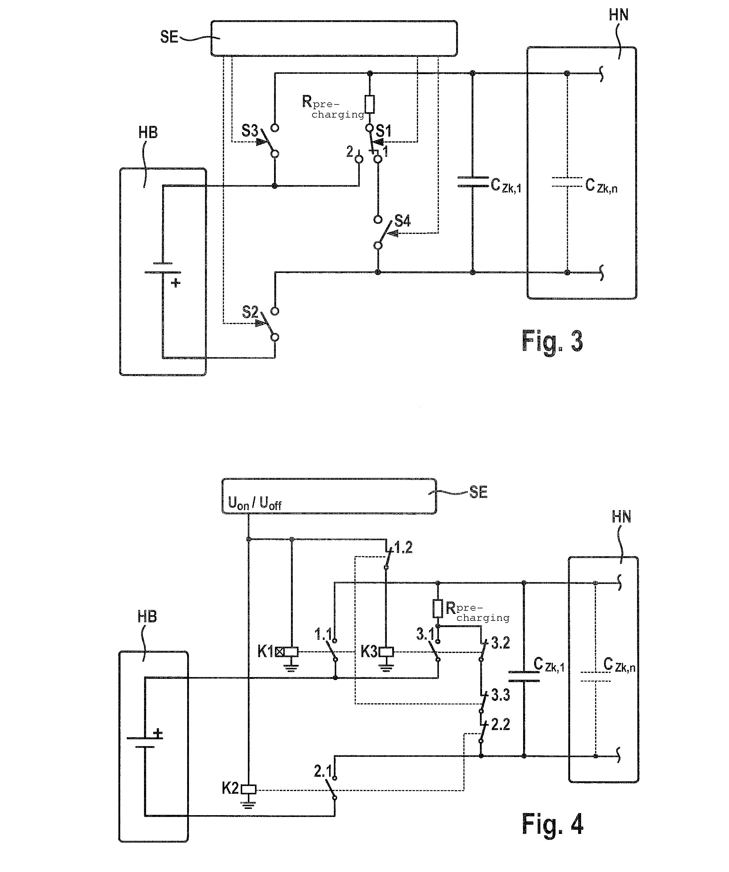
An embodiment variant 2 is shown in FIGS. 4 and 5. The high-voltage network, in this case, is switched on and off in a controlled manner via control unit SE. In the intermediate circuit discharge in the circuit shown in FIG. 4, the discharge takes place via a precharging resistor in the plus branch of high-voltage battery HB, and FIG. 5 shows a circuit for the intermediate circuit discharge via a precharging resistor in the minus branch of high-voltage battery HB.

Charging process: Contactors K2 and K3 are activated by actuation signal UON of control unit SE, that is, make contacts 2.1 and 3.1 of contactors K2 and K3 are closed, while break contacts 2.2 and 3.2 are correspondingly opened. Contactor K1 is activated via actuation signal UON of the control unit, but switches on only after the expiration of the pickup delay time. The capacitors in DC voltage intermediate circuit CZk,1 to CZk,n are charged via precharging resistor Rprecharging. After the expiration of the pickup delay tim...


PUM


Abstract

Methods and associated devices are described for discharging the high-voltage network, particularly a DC voltage intermediate circuit, in which for discharging the capacitors of the high-voltage network, switching devices are used that lie between the capacitors and at least one precharging resistor and a high-voltage battery, and the switching devices are switches having a specifiable positioning of the switching contacts or switching units or relays or contactors, which are switchable with the aid of a control device. The operation of the switching units takes place in such a way that the at least one precharging resistor is used simultaneously for charging and discharging the DC voltage intermediate circuit.

Description

FIELD OF THE INVENTIONThe present invention relates to a method and devices for discharging the high-voltage network, especially in a hybrid vehicle or an electric highway vehicle.BACKGROUND INFORMATIONIn a hybrid vehicle and an electric highway vehicle voltages are used that are greater than 60 V DC. These voltages are designated as being high voltage in the vehicle, and they are the cause of dangerous leakage currents. The high voltage network, also called DC voltage intermediate circuit, in a hybrid vehicle and an electric highway vehicle, in the simplest case is made up of a battery, a voltage inverter having a DC voltage intermediate circuit capacitor, and one or more electric machines, additional high voltage consumers such as an electric climate control compressor and a cable harness which connects all the high voltage components to one another. The voltage inverter requires a DC voltage intermediate circuit capacitor for its functioning, having a sufficiently great capacitan...

Claims


Application Information

Patent Timeline
IPC IPC(8): H01M10/46H02J7/00
CPCB60L3/0007B60L3/0046B60L3/0053B60L3/0092B60L3/04Y02T90/34B60L11/1803H02M1/36Y02T10/7005Y02T10/7022B60L11/005B60L50/40B60L50/51H02M1/322Y02T10/70Y02T90/40
Inventor DITTMER, BERNDWINTER, ARNOLDMIKULEC, DRAGAN
Owner ROBERT BOSCH GMBH
Why Eureka
Try Eureka