
Insulated clamp

a technology of insulated clamps and clamps, which is applied in the direction of snap fasteners, machine supports, buckles, etc., can solve the problems of reducing the efficiency of insulating, and preventing condensation from accumulating on the underside of the pipe attached to the c-channel. , to achieve the effect of reducing time and money and preventing condensation

Active Publication Date: 2011-01-13
HANCOCK DANIEL J
View PDF19 Cites 4 Cited by
  • Summary
  • Abstract
  • Description
  • Claims
  • Application Information

AI Technical Summary

Benefits of technology

"The present invention is an insulated clamp for commercial pipes that prevents sweating and accumulation of condensation. It is made of a flexible solid material and securely encases a pipe at the interface area where it is secured to a C-channel. The clamp includes flanges that fit around the curvature of a pipe and a rod member or other similar device that can move between the flanges. The clamp is secured to the C-channel using fastening members that align with apertures in the rod member and a lip, edge, or side portion of the C-channel. The clamp is sturdy and provides a fully insulated seal around the pipe, preventing condensation accumulation and reducing time and money associated with securing pipes to a C-channel. The invention can be modified to secure other structures."

Problems solved by technology

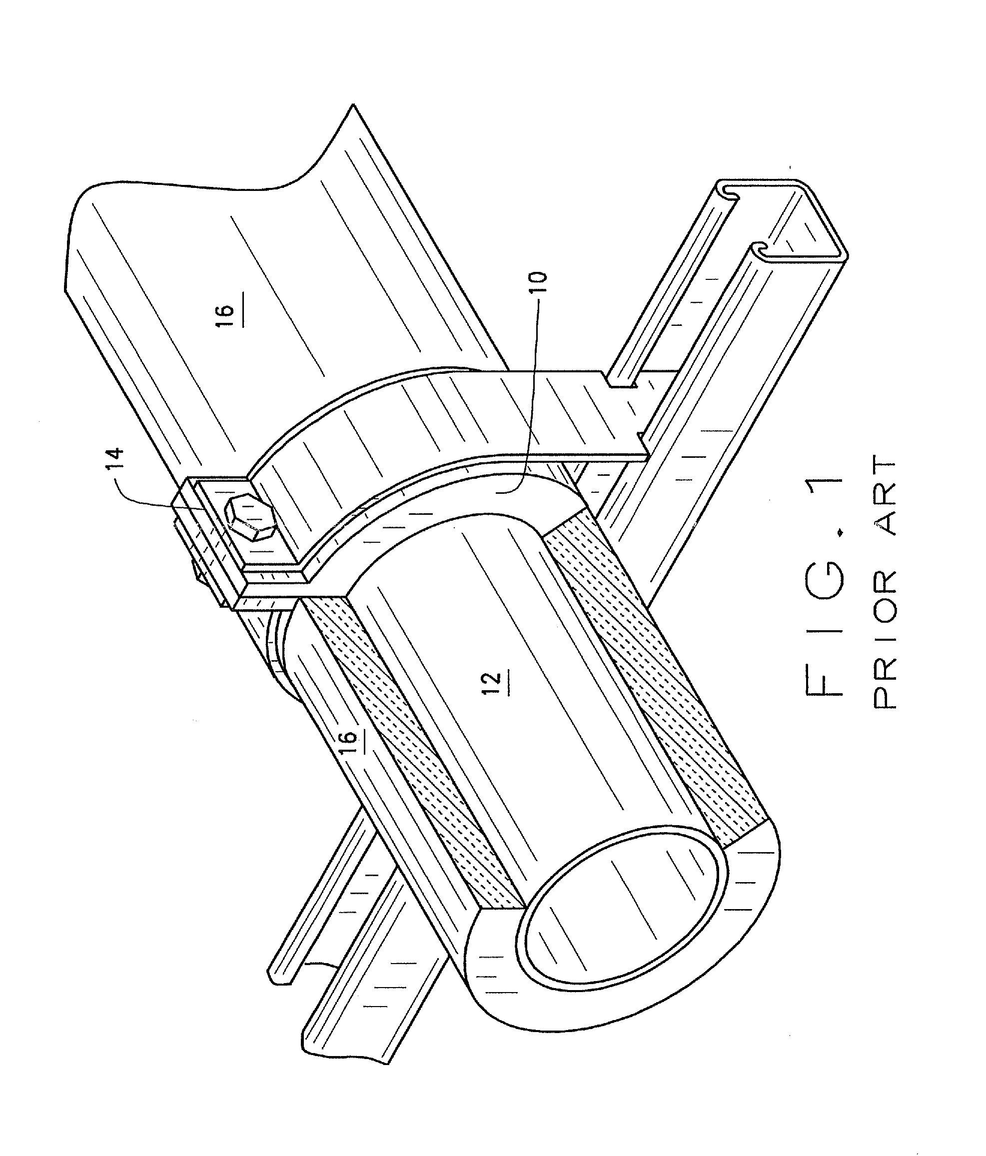
Unfortunately, prior art clamps typically do not insulate that portion of the pipe to which the clamp is secured, that is, the clamp / pipe interface.
Often, this portion of the pipe is left uninsulated or in some applications, as explained below, it is covered with a spray-type insulation, or with an insulation material that is merely inserted in the clamp / pipe interface area, which insulation compresses and / or becomes a less efficient insulator over time due to how it is installed in the interface area.
However, in this prior art method, the underneath side of the pipe attached to the C-channel remains un-insulated.
This solution is time consuming and does not always completely cover the underneath side of the pipe nor does it always prevent condensation.
Specifically, Armaflex® insulation will compress over time, thereby causing gaps in the insulation and / or allowing movement of the pipe within the clamp.
Such solutions may provide insulation, however the amount of insulation is typically limited.
As such, the insulation at the clamped portion of the pipe is generally minimal in comparison to the un-clamped portion of the pipe, thereby decreasing the efficiency of the insulation.
Also, the insulated sleeves are typically subject to compression, causing gaps and / or allowing movement of the pipe.
Moreover, these known methods require addition supplies, thereby resulting in additional costs and time required to install and insulate the pipe.

Method used


Image

  • Insulated clamp
  • Insulated clamp
  • Insulated clamp

Examples


Embodiment Construction

[0023]The following description of the various embodiment(s) of the present invention is merely exemplary in nature and is in no way intended to limit the invention, its application, or uses.

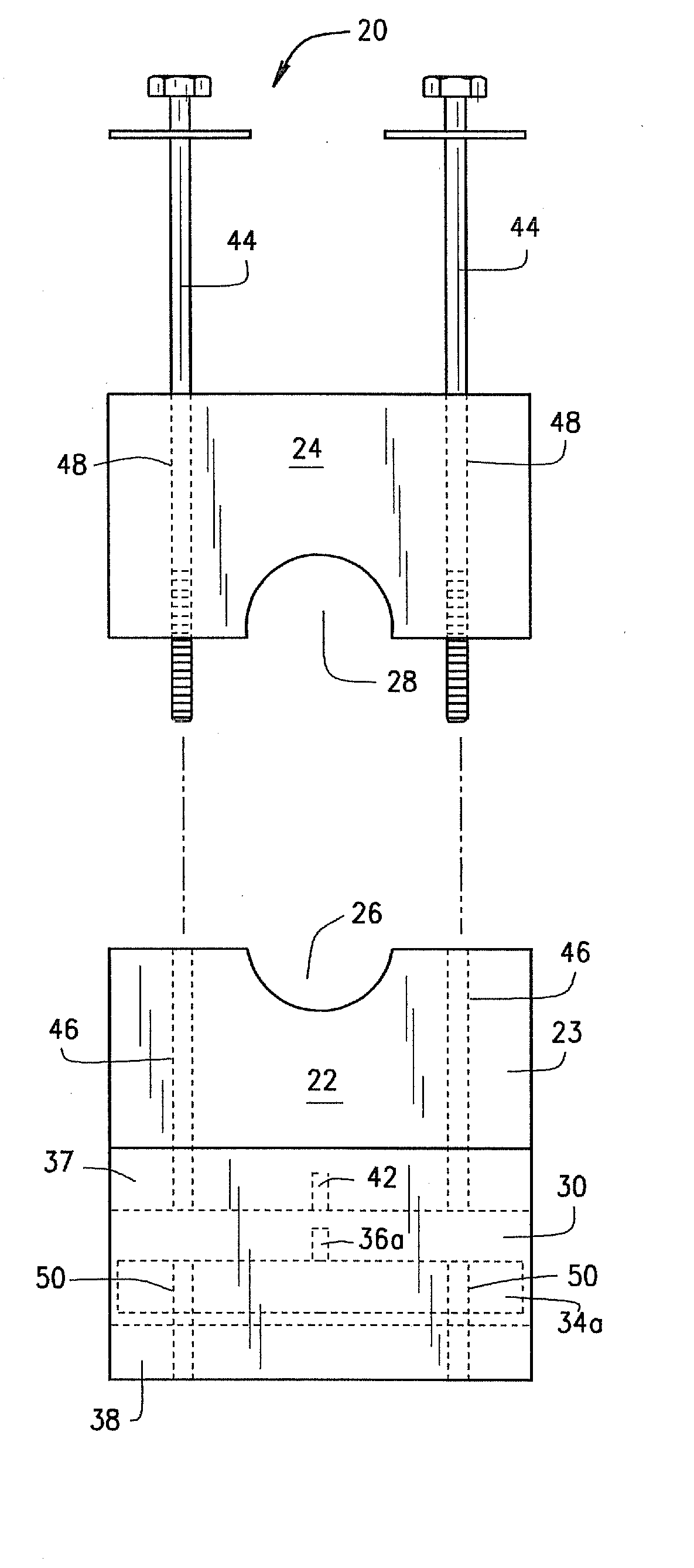
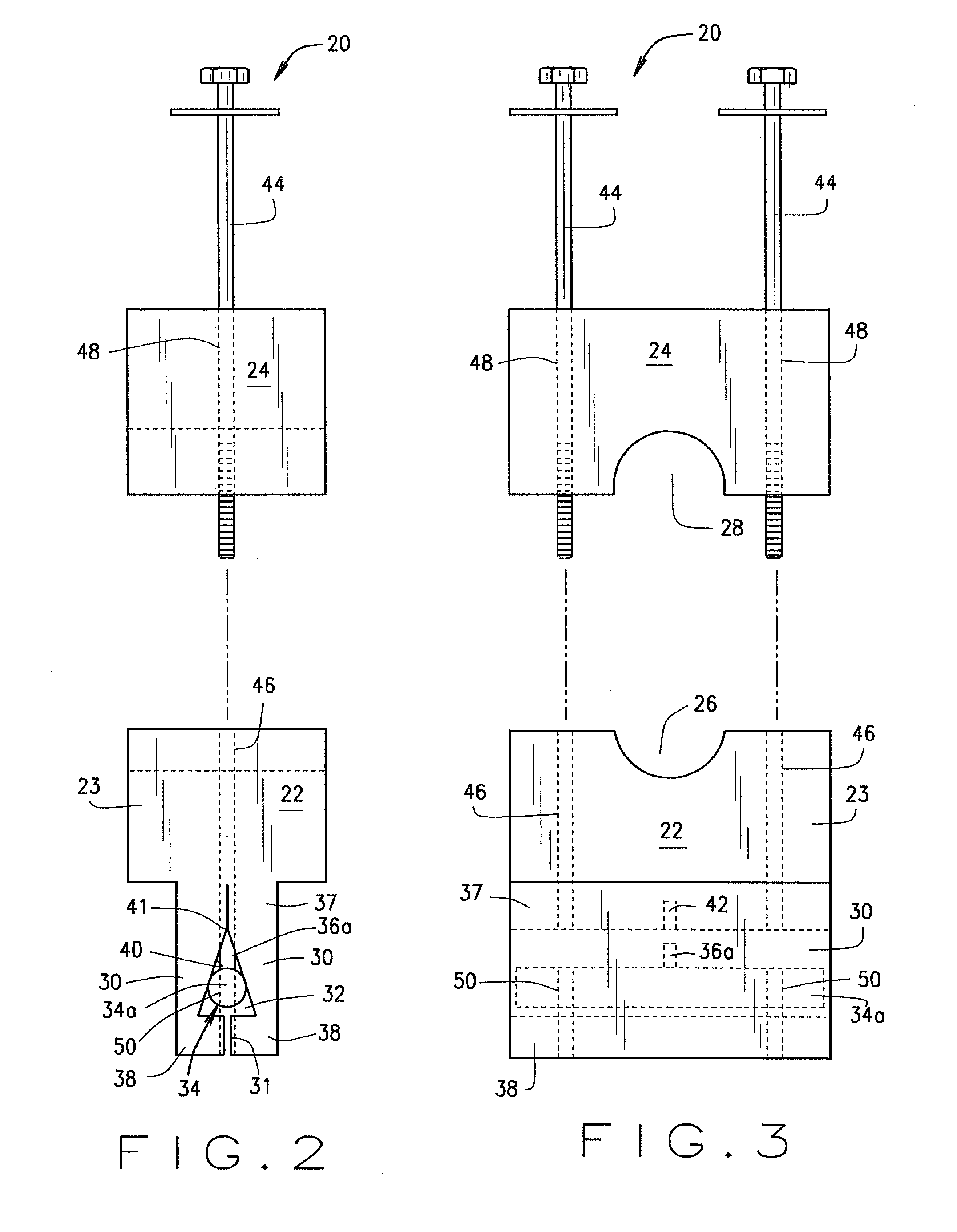
[0024]FIGS. 2-5 illustrate one embodiment of an insulated clamp device 20 constructed in accordance with the teachings of the present invention. FIGS. 6-9 illustrate a second embodiment of the present clamp device 20′. Unless otherwise indicated, the first and second embodiments are substantially the same and like parts are referenced using the same reference numbers.

[0025]Clamp 20 in FIGS. 2-5 includes a first portion 22 and a second portion 24, each formed from an insulating material such as, but not limited to, a high density rubber material. First portion 22 and second portion 24 are configured to mate and couple together so that a pipe may be securely held therebetween. Specifically, first portion 22 and second portion 24 each include a recess 26 and 28 respectively, the recesses being posi...


PUM


Abstract

An insulated clamp for securing a pipe to a conventional C-channel including first and second portions each having a recess associated therewith for receiving a portion of a pipe to be positioned therebetween, the first portion including a pair of flanges receivable within the C-channel, an expansion device positioned between the pair of flanges for moving the flanges into engagement with the C-channel, and a coupling mechanism for attaching the first and second portions to each other. The coupling mechanism is engageable with the expansion device to move the pair of flanges into their engaged position with the C-channel when the first and second clamp portions are attached to each other.

Description

BACKGROUND OF THE INVENTION[0001]The present invention relates to an insulated clamp and, more particularly, to an insulated clamp for use in securing a variety of different types of pipe such as domestic water pipes, heating hot water pipes, refrigeration pipes, and low temperature pipes to name a few to a conventional C-channel.[0002]Prior art pipe hanging applications typically utilize a C-shaped metal channel (“C-channel”) that is installed along the length of a ceiling or other ceiling type structure. The mechanical piping is laid across the C-channel and secured with metal clamps. Once attached to the C-channel, all pipe systems are typically insulated. This is to provide energy efficiency in the case of heating hot water pipes, or to prevent condensation in the case of refrigeration piping, low temperature piping, and some domestic water piping. After installation of the pipe and clamps, the portions of the pipe extending away from the C-channel on both opposite sides thereof...

Claims


Application Information

Patent Timeline
Patent Type & Authority Applications(United States)
IPC IPC(8): A44B21/00
CPCF16L59/135Y10T24/44026F16L3/24F16L3/1091F16L3/243
Inventor HANCOCK, DANIEL J.
Owner HANCOCK DANIEL J
Learn More