
Acoustic crystal sonoluminescent cavitation devices and ir/thz sources

a technology of sonoluminescent cavitation and ir/thz source, which is applied in the direction of mechanical vibration separation, nuclear reactors, greenhouse gas reduction, etc., can solve the problems that many aspects of the phenomena have not yet been characterized, and achieve the effect of efficient rou

Active Publication Date: 2011-01-06
RAYTHEON CO
View PDF10 Cites 16 Cited by
  • Summary
  • Abstract
  • Description
  • Claims
  • Application Information

AI Technical Summary

Benefits of technology

[0015]The present invention uses an acoustic crystal structure to enhance sonoluminescence. Defect cavities in the crystal structure concentrate the driving pressure from applied sound waves into the cavity to cavitate gas bubbles in a liquid to produce sonoluminescence. A waveguide may be coupled to the acoustic crystal to extract, collect and route a band of electromagnetic (EM) radiation around a specified source wavelength to an output port for emission by an antenna to provide an EM source. The marriage of the sonoluminescence phenomena with an acoustic crystal provides for an efficient source of narrow or broad band IR or THz radiation
[0017]In an embodiment, a sonoluminescent EM source comprises a waveguide operatively coupled an acoustic crystal sonoluminescent cavitation device to extract, collect and route a band of electromagnetic (EM) radiation around a specified source wavelength to an output port for emission by an antenna to provide an EM source. Sonoluminescence in the defect cavity produces very high temperatures, hence elevated black-body radiation. At these high temperatures an inert gas is used to sustain sonoluminescence. The waveguide provides the means to extract a specified band of wavelengths, collect the radiation from the at least one defect cavity (typically multiple defect cavities) and efficiently route the collected radiation to an output for emission. The waveguide is on a much smaller scale than the acoustic crystal to avoid interfering with the coupling of the sound waves to the defect cavities. The waveguide may, for example, be a photonic crystal defect waveguide, a photonic crystal optical fiber or a Sommerfeld waveguide. Multiple waveguides tuned to different source wavelengths may be coupled to a single acoustic crystal sonoluminescent device. The marriage of the sonoluminescence phenomena with an acoustic crystal provides for an efficient source of narrow or broad band IR or THz radiation

Problems solved by technology

Although it is generally recognized that during the collapse of a cavitating bubble extremely high temperature plasmas are developed, leading to the observed sonoluminescence effect, many aspects of the phenomena have not yet been characterized.

Method used


Image

  • Acoustic crystal sonoluminescent cavitation devices and ir/thz sources
  • Acoustic crystal sonoluminescent cavitation devices and ir/thz sources
  • Acoustic crystal sonoluminescent cavitation devices and ir/thz sources

Examples


Embodiment Construction

[0028]The present invention describes an acoustic crystal structure for enhancing sonoluminescence. Defect cavities in the crystal structure concentrate the driving pressure from applied sound waves into the cavity to cavitate gas bubbles in a liquid in the defect cavity to produce sonoluminescence. A waveguide may be coupled to the acoustic crystal to extract, collect and route a band of electromagnetic (EM) radiation around a specified source wavelength to an output port for emission by an antenna to provide an EM source. The marriage of the sonoluminescence phenomenon with an acoustic crystal provides for an efficient source of narrow or broad band IR (approximately 1 micron to 30 micron) or THz (approximately 300 GHz to 4 THz) radiation. By convention IR sources are referred to in terms of wavelength while THz sources are referred to in terms of frequency.

[0029]As used herein a ‘sound wave’ refers to a pressure fluctuation that travels through a medium (solid, liquid or gas) at ...


PUM

PropertyMeasurementUnit
Lengthaaaaaaaaaa
Lengthaaaaaaaaaa
Lengthaaaaaaaaaa

Abstract

An acoustic crystal structure includes defect cavities that concentrate the driving pressure from applied sound waves into the cavities to cavitate gas bubbles in a liquid to produce sonoluminescence. This device may be used to study sonoluminescence or cavitation or to perform sonochemistry, nuclear fusion etc. in the cavities. A waveguide may be operatively coupled to the acoustic crystal to extract, collect and route a band of electromagnetic (EM) radiation around a specified source wavelength to an output port for emission by an antenna to provide an EM source. The waveguide may, for example, be a photonic crystal defect waveguide, a photonic crystal optical fiber or Sommerfeld waveguide. The marriage of the sonoluminescence phenomena with an acoustic crystal and embedded waveguide provides for an efficient source of narrow or broad band IR or THz radiation

Description

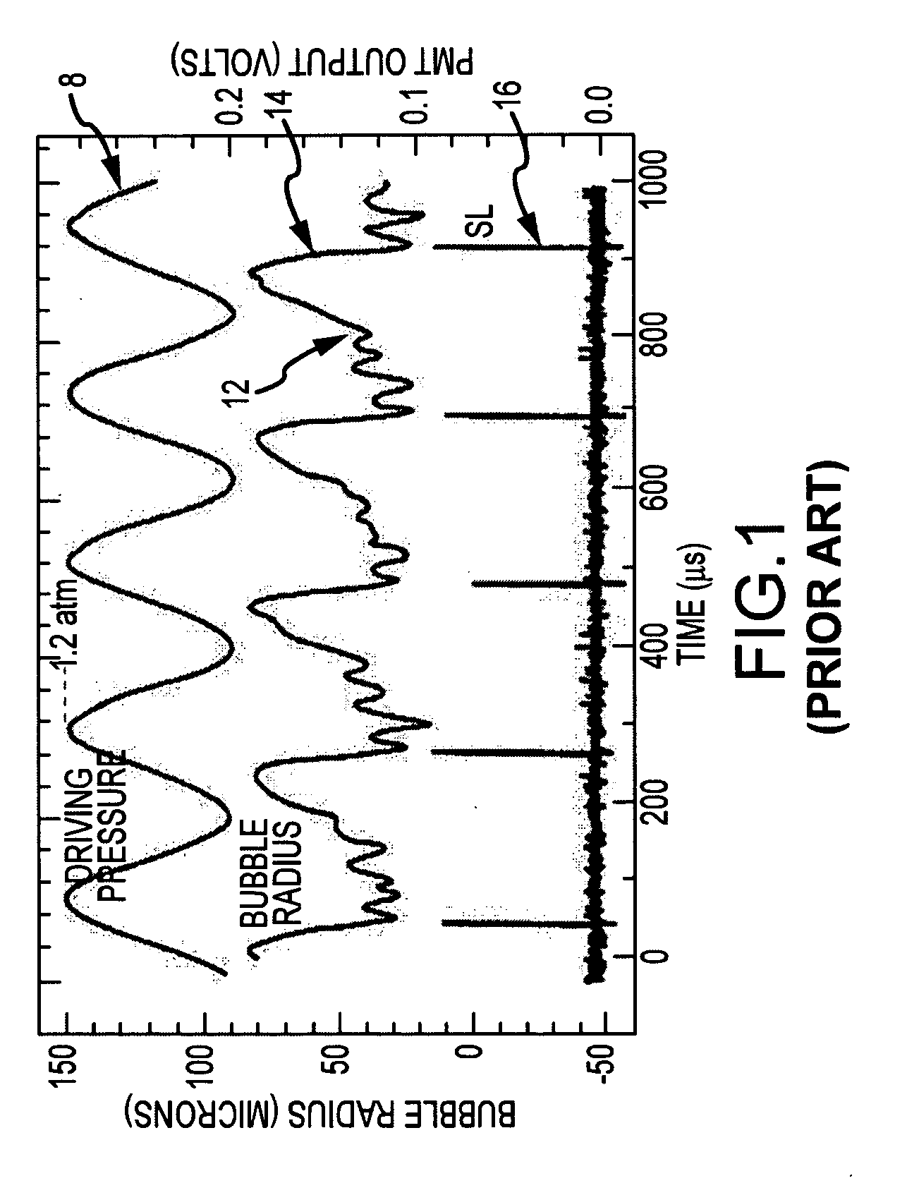
BACKGROUND OF THE INVENTION[0001]1. Field of the Invention[0002]This invention relates to sonoluminescent cavitation devices and to their use as sources of infrared (IR) or terahertz (THz) radiation.[0003]2. Description of the Related Art[0004]Sonoluminescence is a well-known phenomenon discovered in the 1930's in which light is generated when a liquid is cavitated. Although a variety of techniques for cavitating the liquid are known (e.g., spark discharge, laser pulse, flowing the liquid through a Venturi tube), one of the most common techniques is through the application of high intensity sound waves.[0005]In essence, as shown in FIGS. 1 and 2 the cavitation process consists of three stages that are driven by the application of high intensity sound waves 8; bubble formation 10, growth 12 and subsequent collapse 14 that emits a flash or pulse of light 16. The bubble or bubbles cavitated during this process absorb the applied energy, for example sound energy, and then release the en...

Claims


Application Information

Patent Timeline
IPC IPC(8): G21G4/00
CPCY02E30/18G21B3/00Y02E30/10
Inventor BARKER, DELMAR L.OWENS, WILLIAM R.
Owner RAYTHEON CO
Learn More