
Methods and apparatus for predictive preventive maintenance of processing chambers

a technology of pre-determined maintenance and processing chamber, which is applied in the direction of analogue processes, instruments, and specific applications using reradiation, etc., can solve the problems of affecting the useful life of components

Active Publication Date: 2010-12-30
LAM RES CORP
View PDF99 Cites 44 Cited by
  • Summary
  • Abstract
  • Description
  • Claims
  • Application Information

AI Technical Summary

Problems solved by technology

Over time, one or more components may wear out.
Those skilled in the art are aware that worn-out components may cause damage to the chamber and / or damage to the substrate if the worn-out components are not fixed / replaced.
Unfortunately, the method of predetermining the useful life of a component for replace / repair purposes has its limitations.
Thus, with the predetermined useful life method, unnecessary costs associated with taking a processing chamber offline and replacing a component may be incurred even though the component's useful life may not have actually ended.
In addition, the predetermined useful life method may not account for the possibility of the component prematurely wearing out before the expiration of its predetermined theoretical useful life.
In many instances, the component's deteriorating condition may result in damaged substrates and / or even damage to the chamber and other components within the processing chamber.
Unfortunately, the uni-variate method also has its limitations.
However, the value of the RF bias voltage may be affected by influences other than just the edge ring condition.
Instead, a problem may exist but further analysis may be required before the cause of the problem can be identified.
Another problem with the uni-variate method is that the uni-variate method can be a “go / no-go” method.
However, the uni-variate method may be unable to assist in predicting when (instead of whether) the component may need to be replaced.
Consequently, when a component, such as the edge ring, does actually wear out, a replacement component may not be immediately available.
This method of always carrying spare components can become expensive since the manufacturing company has to allocate resources (money and storage space) to have components available even if the components are still in proper working condition.
There are several limitations with the monitoring patch method.
The monitoring patch method can become very expensive and time consuming to implement and monitor depending upon the number of components that may be monitored.
Also, the utilization of a monitoring patch may increase the risk of contamination.
In addition, the degree with which the processing environment may have changed due to the existence of the monitoring patches within the processing chamber may be unknown or difficult to measure.
Another limitation of the monitoring patch method is that by placing a monitoring patch onto a component, the mechanical functionality of the component may be compromised.
Unfortunately, the extent at which the patch may have altered the functionality of the component may vary since each component and / or each patch may be unique.

Method used


Image

  • Methods and apparatus for predictive preventive maintenance of processing chambers
  • Methods and apparatus for predictive preventive maintenance of processing chambers
  • Methods and apparatus for predictive preventive maintenance of processing chambers

Examples


Embodiment Construction

[0022]The present invention will now be described in detail with reference to a few embodiments thereof as illustrated in the accompanying drawings. In the following description, numerous specific details are set forth in order to provide a thorough understanding of the present invention. It will be apparent, however, to one skilled in the art, that the present invention may be practiced without some or all of these specific details. In other instances, well known process steps and / or structures have not been described in detail in order to not unnecessarily obscure the present invention.

[0023]Various embodiments are described hereinbelow, including methods and techniques. It should be kept in mind that the invention might also cover articles of manufacture that includes a computer readable medium on which computer-readable instructions for carrying out embodiments of the inventive technique are stored. The computer readable medium may include, for example, semiconductor, magnetic, ...


PUM


Abstract

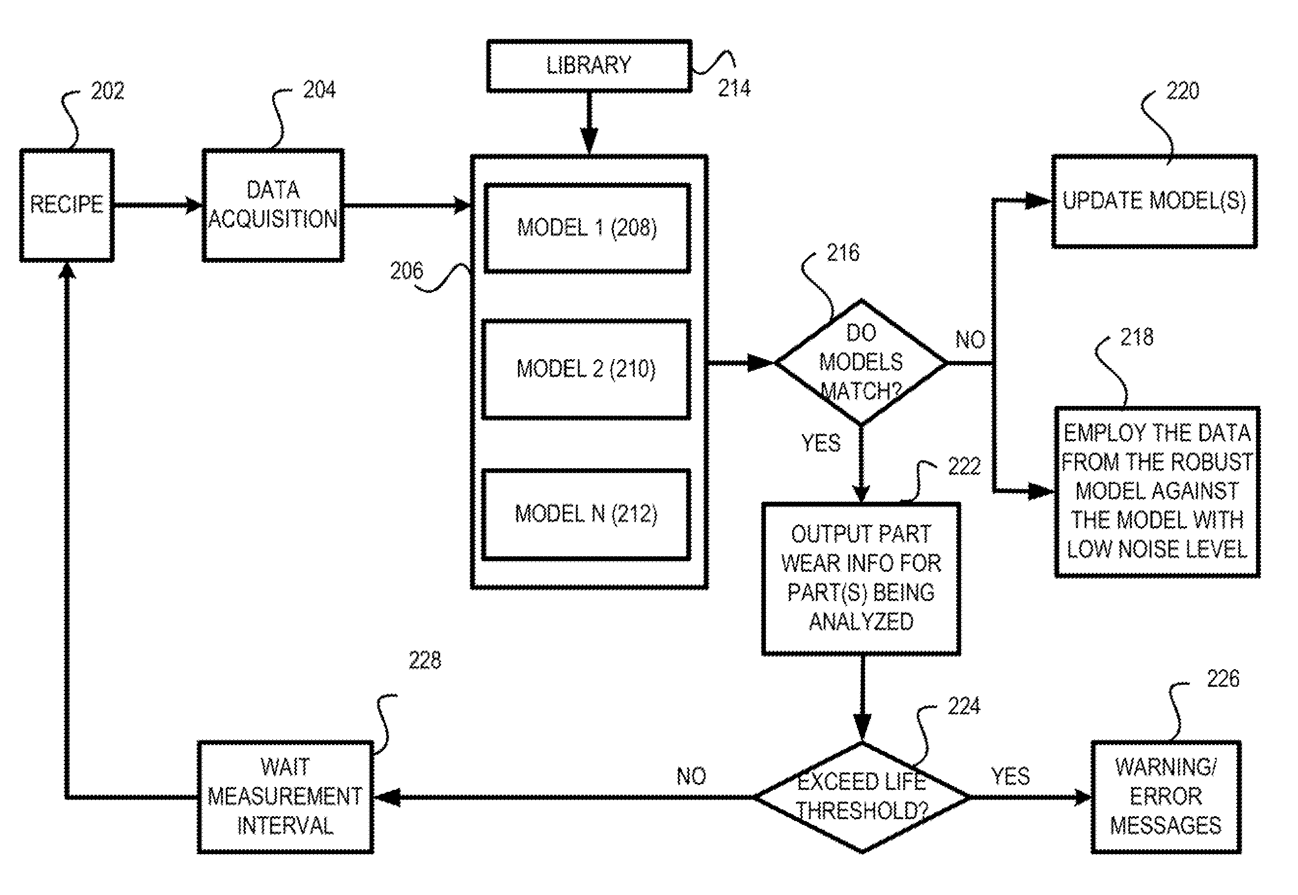
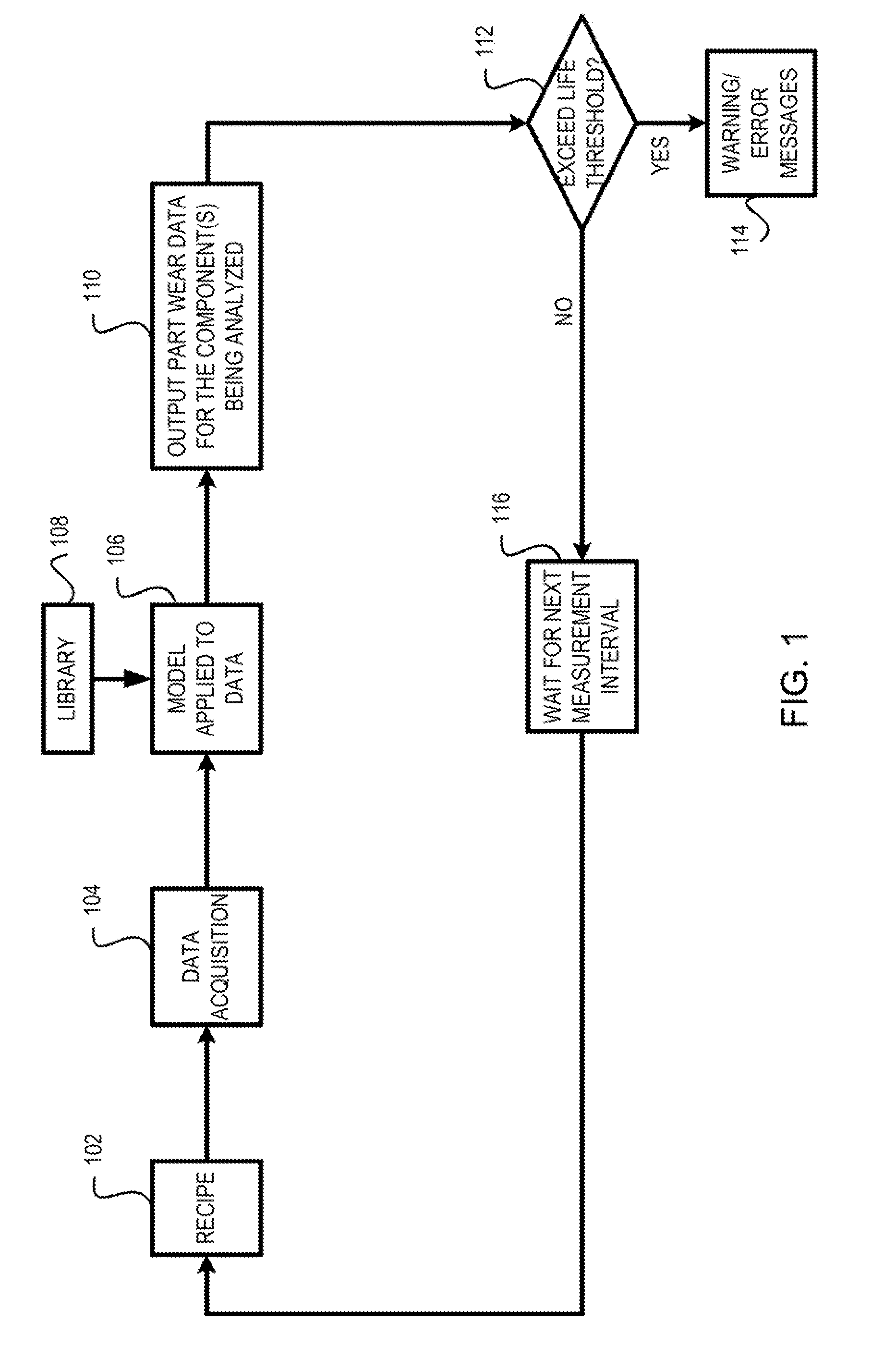
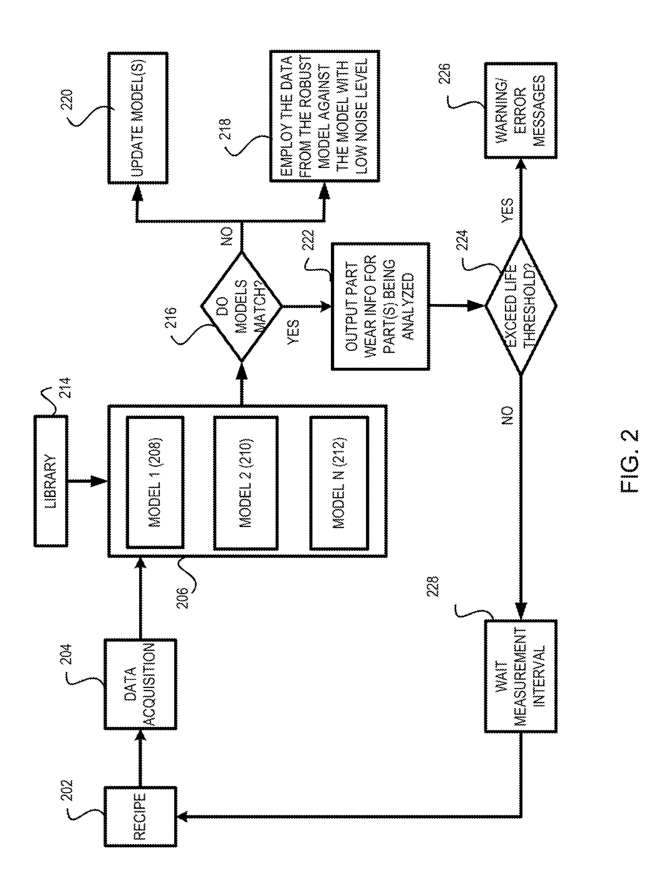
A method for assessing health status of a processing chamber is provided. The method includes executing a recipe. The method also includes receiving processing data from a set of sensors during execution of the recipe. The method further includes analyzing the processing data utilizing a set of multi-variate predictive models. The method yet also includes generating a set of component wear data values. The method yet further includes comparing the set of component wear data values against a set of useful life threshold ranges. The method moreover includes generating a warning if the set of component wear data values is outside of the set of useful life threshold ranges.

Description

CROSS REFERENCE TO RELATED APPLICATIONS[0001]The present invention claims priority under 35 U.S.C. 119(e) to a commonly owned provisionally filed patent application entitled “Methods and Systems for Advance Equipment Control / Advance Process Control for Plasma Processing Tools,” U.S. Application No. 61 / 222,102, Attorney Docket No. P2012P / LMRX-P183P1, filed on Jun. 30, 2009, by inventors Venugopal et al., all of which is incorporated herein by reference.[0002]This continuation-in-part application claims priority under 37 CFR 1.53(b) of and claims the benefit under 35 U.S.C. §120 to a commonly assigned patent application entitled “Arrangement for Identifying Uncontrolled Events of the Process Module Level and Methods Thereof,” by Huang et al., Attorney Docket Number P2002 / LMRX-P179, application Ser. No. 12 / 555,674 filed on Sep. 8, 2009, which is related to and claims priority under 35 U.S.C. §119(e) to a commonly assigned provisional patent application entitled “Arrangement for Identif...

Claims


Application Information

Patent Timeline
IPC IPC(8): G06F17/10G06G7/62
CPCH01J37/32935H01J37/32477
Inventor ALBAREDE, LUCPAPE, ERICVENUGOPAL, VIJAYAKUMAR C.CHOI, BRIAN D.
Owner LAM RES CORP
Learn More