
Vibration analysis for predictive maintenance in machinery

a predictive maintenance and vibration analysis technology, applied in the direction of machines/engines, liquid/fluent solid measurement, instruments, etc., can solve the problems of insufficient period during which equipment runs at a constant speed and is normally insufficient for vibration analysis to be performed, and attracted little attention

Inactive Publication Date: 2006-08-29
SHELL OIL CO
View PDF3 Cites 44 Cited by
  • Summary
  • Abstract
  • Description
  • Claims
  • Application Information

AI Technical Summary

Benefits of technology

[0024]Preferably, at least one of the groups of identified portions of data are processed to produce data rep

Problems solved by technology

However, an area that has attracted little attention is that of the analysis of frequently reversing drives, particularly such as found in rotating and reciprocating machinery.
No techniques are currently known for the successful analysis of equipment vibrations whilst that equipment is accelerating or decelerating and for differentiation between vibration signatures in the forward and reverse directions.
Another reason for the limited analysis of frequently reversing drives is that the period during which the equipment runs at a constant speed is normally insufficient for vibration analysis to be performed.

Method used


Image

  • Vibration analysis for predictive maintenance in machinery
  • Vibration analysis for predictive maintenance in machinery
  • Vibration analysis for predictive maintenance in machinery

Examples


embodiment

General Embodiment

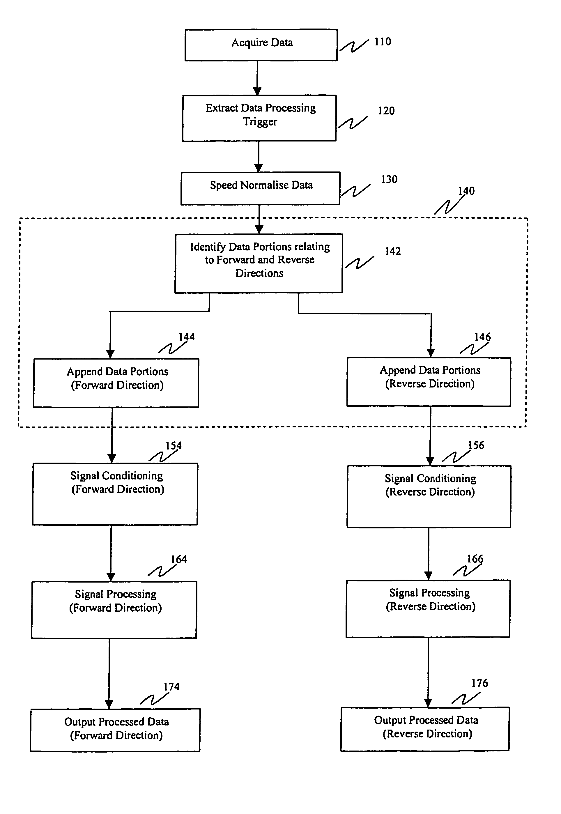
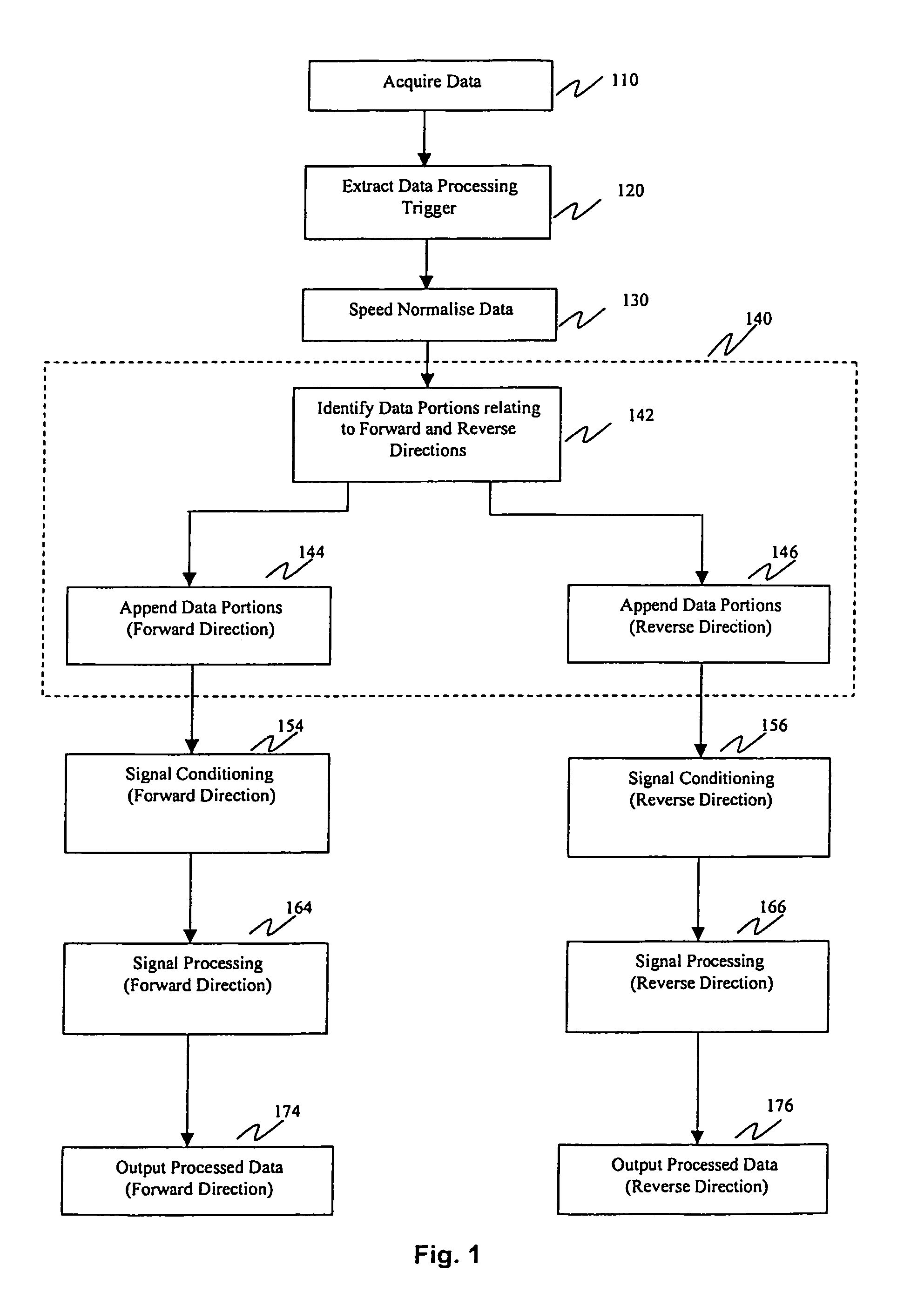
[0140]FIG. 1 is a flow diagram of a general method of vibration analysis for application to a reversible drive.

[0141]Vibration data from a transducer, such as an accelerometer, and shaft speed, direction and position data from one or more transducers, such as a tachometer, are acquired at step 110.

[0142]At step 120, a data processing trigger is extracted from the acquired data. The trigger relates to a reference point on the shaft of interest and facilitates further data processing. Specifically, the trigger facilitates identification of portions of the data relating to each direction of travel of the shaft of interest and identification of constant speed data. Determination of the trigger and direction of rotation of the shaft of interest are further described later in this document.

[0143]At step 130, the data is speed normalised. This includes resampling of the data for transformation from the time domain into the angle domain. At the same time, samples relating ...


PUM


Abstract

A method for detecting vibration signatures in a reversible drive is disclosed. The method includes the steps of acquiring digital data representative of vibrations in the reversible drive and identifying and grouping together portions of data in a plurality of groups. The identified portions of data relate to a particular direction of travel of the reversible drive and the plurality of groups relate to travel in different directions of the reversible drive. The method can include the further step of processing at least one of the groups of data using signal processing techniques. A system and computer program product for practicing the method for detecting vibration signatures in a reversible drive are also disclosed.

Description

FIELD OF THE INVENTION[0001]The present invention relates generally to vibration analysis in machinery and more specifically to vibration analysis, for purposes of predictive maintenance, in rotating, reciprocating and cyclic machinery.BACKGROUND OF THE INVENTION[0002]Predictive maintenance aims to sustain the availability of equipment and avoid catastrophic failures, which may cause severe consequential damage to other components of the equipment before the equipment can be shut down. The avoidance of catastrophic failures often reduces the number of components to be replaced. Predictive maintenance is further beneficial in that equipment down time can be predicted and scheduled. Thus, unscheduled down time can be minimised and delays that may be incurred due to procurement of spare parts can be avoided.[0003]Rotating and reciprocating machinery represent very commonly found types of equipment found in industry and it is for this reason that extensive work has been conducted on tec...

Claims


Application Information

Patent Timeline
IPC IPC(8): G01F17/00G01H1/08G01H17/00G01H1/00G01M13/02G01M99/00
CPCG01M13/028G01H1/003G01H1/00
Inventor HITCHCOCK, LEITH PATRICKSCHMITZ, NICHOLAS
Owner SHELL OIL CO
Learn More