
Display device, picture signal processing method, and program

a display device and picture signal technology, applied in the field of display devices, can solve the problems of current overflowing into the luminescence elements and the amount of light, and achieve the effect of preventing current and improving display quality

Active Publication Date: 2010-12-30
JOLED INC
View PDF10 Cites 64 Cited by
  • Summary
  • Abstract
  • Description
  • Claims
  • Application Information

AI Technical Summary

Benefits of technology

"The present invention provides a display device, method, and program that can control the luminous time per unit time and the gains of picture signals to achieve higher display quality. By adjusting the reference duty and effective duty, the luminescence amount regulator and adjuster can prevent the current from overflowing into the luminescence elements and achieve higher display quality. The invention also includes an average luminance calculator to set the reference duty based on the average luminance of the input picture signal. Overall, the invention improves the display quality of moving pictures and still images."

Problems solved by technology

However, the typical techniques related to luminous time control for a unit time merely shortens the luminous time per unit time and lower the signal level of a picture signal in response to higher average luminance of the picture signal.
Thus, when a picture signal at extremely high luminance is input into a self-luminescence type display device, the luminescence amount of a picture displayed (signal level of picture signal×luminous time) becomes much too large, which could result in the current overflowing into the luminescence elements.

Method used


Image

  • Display device, picture signal processing method, and program
  • Display device, picture signal processing method, and program
  • Display device, picture signal processing method, and program

Examples


Embodiment Construction

[0090]Hereinafter, preferred embodiments of the present invention will be described in detail with reference to the appended drawings. Note that, in this specification and the drawings, elements that have substantially the same function and structure are denoted with the same reference numerals, and repeated explanation is omitted.

Example of Display Device According to Embodiment of Invention

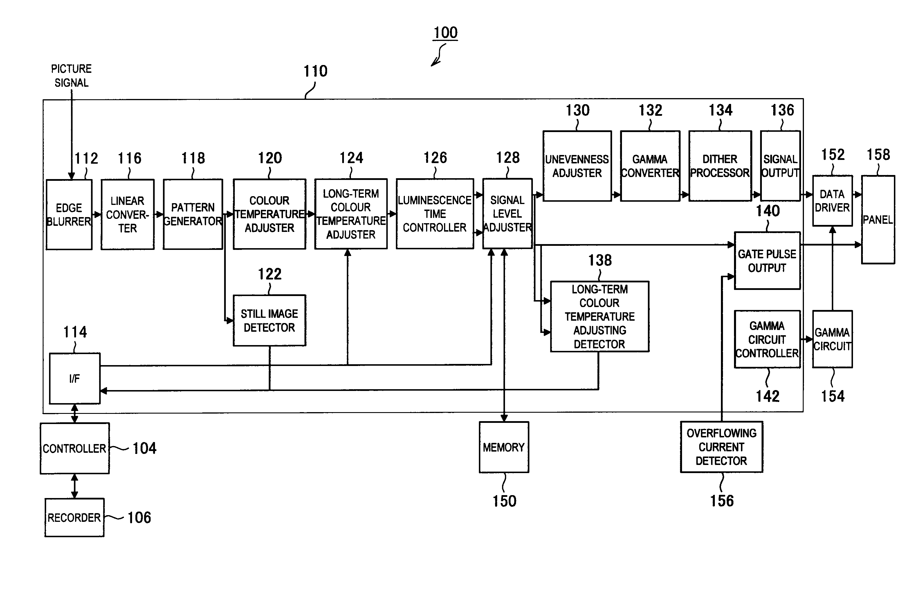
[0091]First, an example of the configuration of a display device according to an embodiment of the present invention will be described. FIG. 1 is an illustration that shows an example of the configuration of the display device 100 according to an embodiment of the present invention. Besides, in the following, an organic EL display, which is a self-luminescence display device, will be described as an example of the display devices according to an embodiment of the present invention. Also, in the following, the explanation will be provided with assumption that a picture signal input into the displ...


PUM


Abstract

Provided is a display device including a display unit having luminescence elements that individually becomes luminous depending on a current amount. The luminescence elements are arranged in a matrix pattern. The display device comprises a luminescence amount regulator for setting a reference duty for regulating a luminescence amount per unit time for each of the luminescence elements, according to picture information of an input picture signal, and also comprises an adjuster for adjusting, based on the reference duty, an effective duty regulating a luminous time for which the luminescence elements become luminous within a unit time, so that the effective duty is within a predetermined range, and for adjusting a gain of the picture signal, so that a luminescence amount regulated with the effective duty and with the gain of the picture signal equals to the luminescence amount regulated with the reference duty.

Description

TECHNICAL FIELD[0001]The present invention relates to a display device, a method of processing a picture signal, and a program.BACKGROUND ART[0002]In recent years, various display devices, such as organic EL displays (organic ElectroLuminescence displays, also called as OLED displays (Organic Light Emitting Diode displays)), FEDs (Field Emission Displays), PDPs (Plasma Display Panels), and the like, have been developed as devices to replace CTR displays (Cathode Ray Tube displays).[0003]Amongst the various display devices mentioned above, the organic EL displays are self-luminescence type display devices that use an electroluminescence phenomenon. They have drawn particular attention of people as devices for the next generation, because they are superior to display devices in their moving image characteristics, viewing angle characteristics, colour reproducibility, etc. The electroluminescence phenomenon is a phenomenon in which the state of an electron of a material (an organic EL ...

Claims


Application Information

Patent Timeline
Patent Type & Authority Applications(United States)
IPC IPC(8): G09G5/10
CPCG09G2320/0233G09G2320/0626G09G2320/0276G09G2300/0866G09G2300/0417G09G2300/0819G09G2320/0666G09G2310/08G09G3/2077G09G2320/0257G09G3/2044G09G3/2011G09G2320/103G09G3/006G09G2300/0842G09G3/3266G09G2320/0247G09G2360/16G09G2320/043G09G2300/0861G09G3/3233G09G3/20G09G3/30
Inventor INOUE, YASUOITO, MASAHIRO
Owner JOLED INC
Learn More