Fluid machinery

Inactive Publication Date: 2010-12-23
DAIKIN IND LTD
View PDF6 Cites 3 Cited by
  • Summary
  • Abstract
  • Description
  • Claims
  • Application Information

AI Technical Summary

Benefits of technology

[0031]In the present invention, the intermediate pressure of the back pressure chamber (53) at the back surface of the first cooperating member (21, 120) is changed according to the pressure state of the operation chamber (C1), and accordingly, the first cooperating member (21, 120) can be thrust against the second cooperating member (22, 110) by an appropriate amount of thrust force.
[0032]Particularly, in the eleventh aspect of the present invention, one of the cylinder (21) and the piston (22) as the two cooperating members (21, 22) can be thrust against the other by the appropriate amount of thrust force. That is, the thrust force to the cylinder (21) can be increased when the pressure of the outside cylinder chamber (C1) is high, for example, to increase the pitching moment causing inclination of the cylinder (21). In reverse, the thrust force to the cylinder (21) can be decreased when the pressure of the outside cylinder chamber (C1) is low. As a result, the sliding loss by the thrust force between the cylinder (21) and the piston (22) can be reduced.
[0033]Further, the lubricant oil is filled in the back pressure chamber (53), which means that the back pressure chamber (53) is filled with non-compressive fluid, and that no gas fluid is present therein. Accordingly, the pumping of the gas fluid can be prevented. That is, gas refrigerant sucking from the back pressure chamber (53) and gas refrigerant forcing into the back pressure chamber (53), which may be caused by pressure change in the operation chamber (C, 100), can be prevented, thereby reducing power loss.
[0034]In the second to fifth aspects of the present invention, the back flow checking mechanism (60) or the throttling mechanism (65) is provided at the oil passage (55). Accordingly, back flow of the lubricant oil when the back pressure chamber (53) is in the high pressure state can be prevented, thereby keeping the back pressure chamber (53) at a predetermined high pressure state. Particularly, in the case where the compression mechanism is the rotary mechanism (20), in driving in which the high pressure, i.e., the discharge pressure is low (for example, in low compression rate driving, start-up, and the like), compression failure caused by upset of the first cooperating member (21), which may be caused when the internal pressure of the casing is lower than the high pressure of the operation chambers (C1, C2, 100), can be avoided. In addition, when a passage having a valve mechanism for discharging the refrigerant from the operation chambers (C1, C2, 100) at the intermediate pressure to the high pressure side is provided, liquid compression can be prevented effectively, and the back pressure chamber (53) can be kept at the predetermined intermediate pressure.
[0035]In the sixth aspect of the present invention, the high pressure of the high pressure chamber (50) works on the first cooperating member (21, 120), so that the first cooperating member (21, 120) can be always thrust against the second cooperating member (22, 110) by the predetermined amount of thrust force. As a result, the behavior of the first cooperating member (21, 120) can be stabilized.
[0036]In the seventh aspect of the present invention, the predetermined amount of pressure of the constant pressure space (42) works on the first cooperating member (21, 120), so that the first cooperating member (21, 120) can be thrust against the second cooperating member (22, 110) by a minimum amount of thrust force. As a result, the behavior of the first cooperating member (21, 120) can be stabilized, and the optimum amount of thrust force can work on the first cooperating member (21, 120) even in a driving condition where the low pressure is high.
[0037]In the eighth aspect of the present invention, the center of gravity of the back pressure chamber (53) is eccentric from the axial center of the drive shaft (33), so that the point of application of the thrust force can agree with the center of action of opposite thrust force against the first cooperating member (21, 120) when the opposite thrust force is maximum. This can prevent pitching of the first cooperating member (21, 120) by small thrust force.
[0038]In the ninth aspect of the present invention, the operation chambers (C1, C2, 100) are located above the end plate (26, 121) of the first cooperating member (21, 120), and accordingly, discharge of the gas refrigerant can be ensured even when the gas refrigerant flows back to the oil passage (55).
[0039]In the tenth aspect of the present invention, both the back surface of the end plate (26, 121) of the first cooperating member (21, 120) and the opposed surface of the housing (17, 130) opposed to the back surface are flat, and therefore, the gas refrigerant can hardly be retained therebetween, thereby reducing oil agitation loss.

Problems solved by technology

Further, when the compression chamber becomes at an abnormal high pressure, the abnormal high pressure is released between the wraps and the opposed end plates to the low pressure side.

Method used


Image

  • Fluid machinery
  • Fluid machinery
  • Fluid machinery

Examples


example embodiment 1

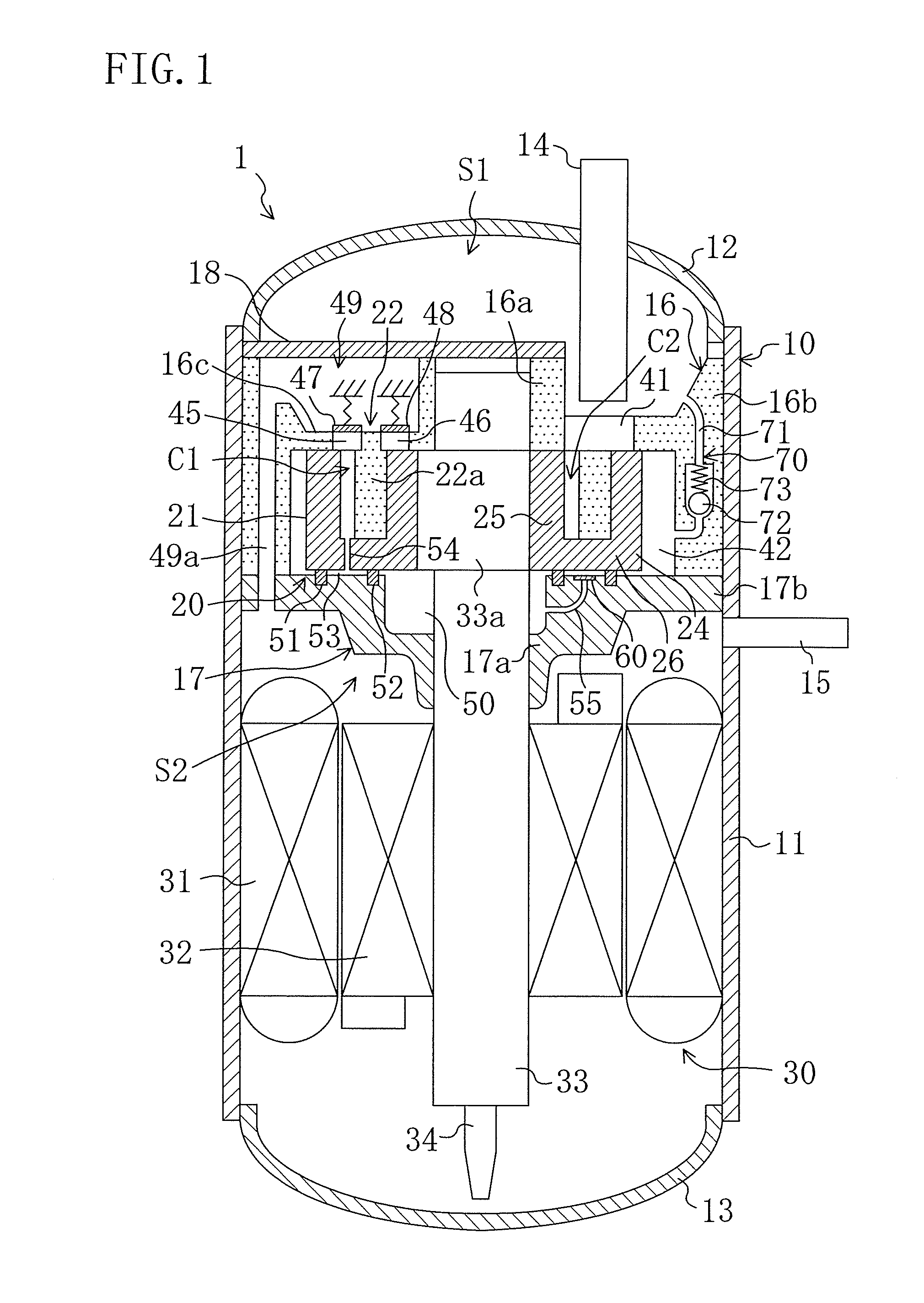
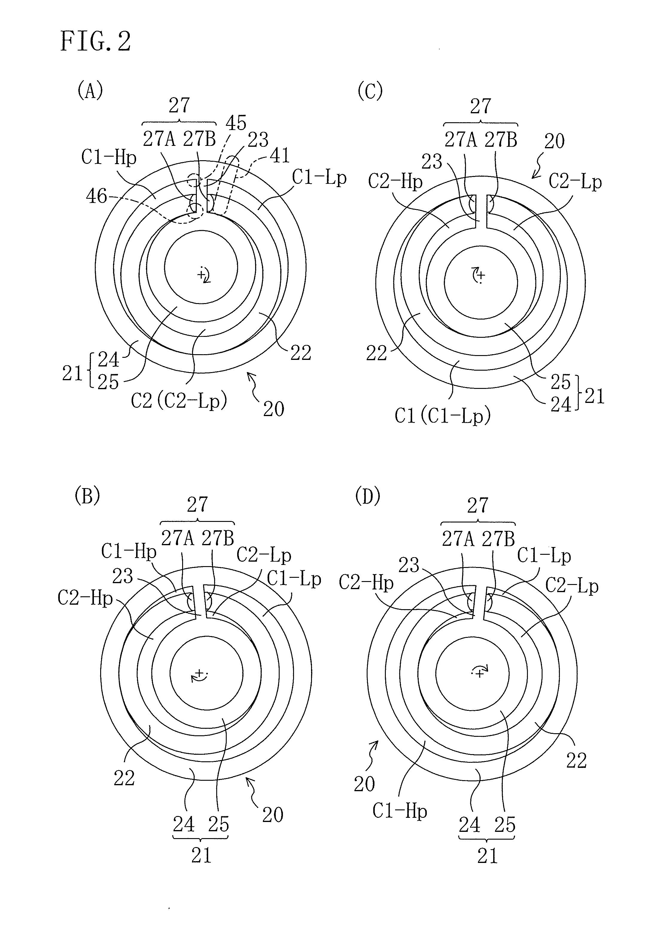
[0071]In the present example embodiment, a rotary compressor (1) is applied to a fluid machinery, as shown in FIG. 1. The compressor (1) is a hermetically sealed compressor. A compression mechanism (20) as a rotary mechanism including an eccentric rotary piston (22) and a motor (30) as a driving mechanism are accommodated inside a casing (10) of the compressor (1). The compressor (1) is provided in a refrigerant circuit of, for example, an air conditioner to compress refrigerant sucked from an evaporator, and discharge it to a condenser.

[0072]The casing (10) includes a cylindrical body part (11), an upper head (12) fixed at the upper end of the body part (11), and a lower head (13) fixed at the lower end of the body part (11). A suction pipe is provided at the upper head (12), while a discharge pipe (15) is provided at the body part (11).

[0073]Inside the casing (10), an upper housing (16) and a lower housing (17) included in the compression mechanism (20) are fixed. Inside the casin...

example embodiment 2

[0121]Example Embodiment 2 of the present invention will be described next in detail with reference to the drawing.

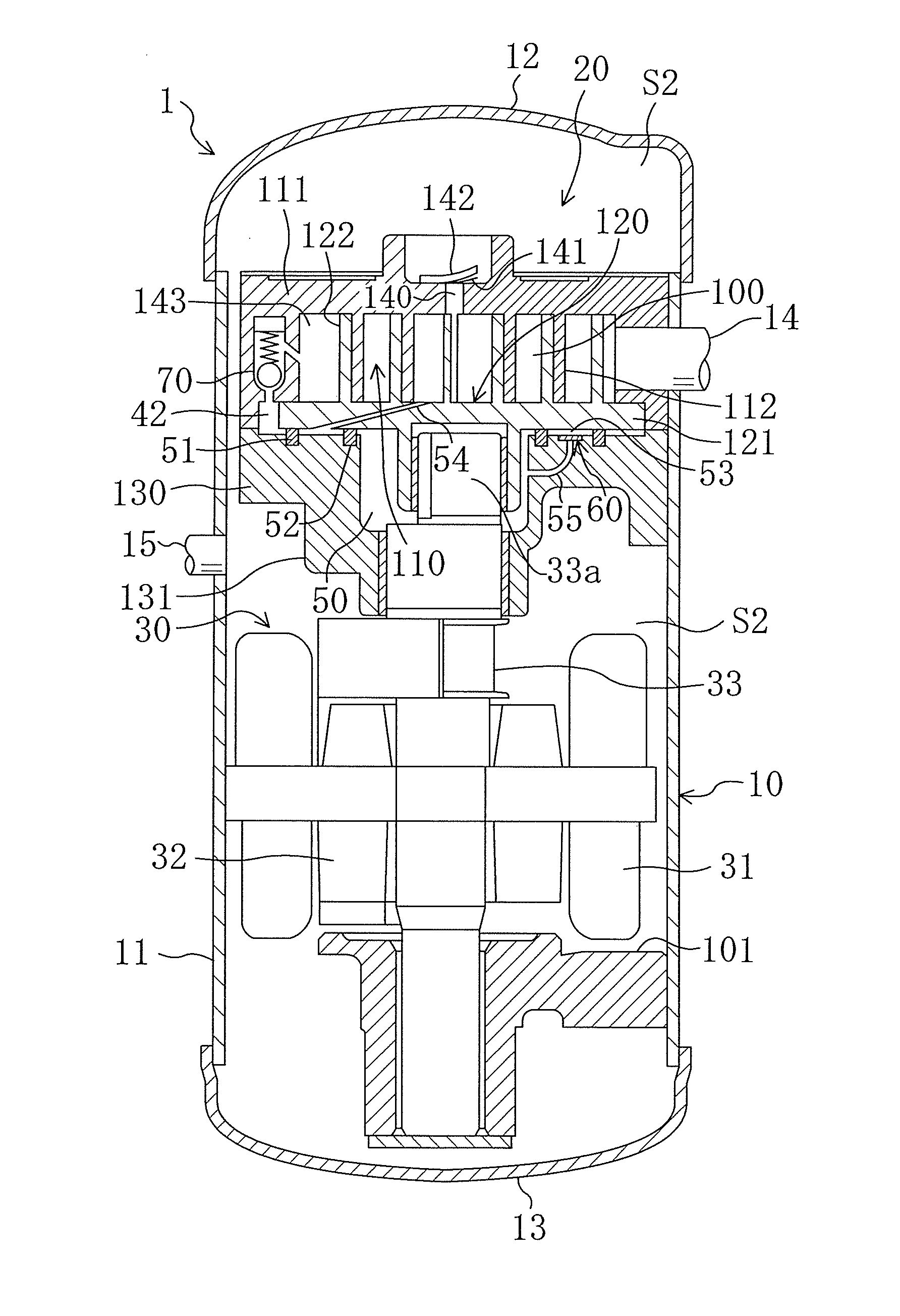
[0122]In the present example embodiment, a scroll compressor as shown in FIG. 7 is employed as the compression mechanism (20) unlike Example Embodiment 1 employing the eccentric rotation type piston mechanism. The inside space of the casing (10) of the rotary compressor (1) in the present example embodiment is defined into an upper space and a lower space by the compression mechanism (20). The upper space and the lower space communicate with each other to serve as the high pressure space (S2).

[0123]The compression mechanism (20) is a rotary mechanism in which a first cooperating member and a second cooperating member perform circulation movement in parallel and relative to each other, and includes a fixed scroll (110) as a second cooperating member, an orbiting scroll (120) as a first cooperating member, and a housing (130). The housing (130) is fixed to the casing (10)...


PUM


Abstract

A fluid machinery includes a rotary mechanism, an annular back pressure chamber and an oil passage. The rotary mechanism includes first and second cooperating members, each including an engaging member extending from an end plate, with the cooperating members being arranged to oscillate relative to each in order to change volumes of operation chambers formed between the cooperating members. The annular back pressure chamber is formed on the back surface side of the end plate of the first cooperating member, and communicates with an intermediate operation chamber of the operation chambers to thrust the first cooperating member against the second cooperating member. The intermediate operation chamber is in an intermediate pressure state. The oil passage is arranged to communicate an oil into the back pressure chamber to fill the back pressure chamber with the oil. The rotary mechanism can include a piston and cylinder, or can include a fixed and orbiting scroll.

Description

TECHNICAL FIELD[0001]The present invention relates to fluid machineries, and particularly relates to a thrust mechanism of cooperating members.BACKGROUND ART[0002]Conventionally, fluid machineries include a scroll compressor used in an air conditioner, as disclosed in Patent Document 1. The scroll compressor includes a fixed scroll and an orbiting scroll including spiral wraps formed on the front surfaces of end plates. In a state that the scroll wraps are in engagement with each other, the orbiting scroll revolves with respect to the fixed scroll without rotating. This revolution compresses the volumes of compression chambers to compress the refrigerant.[0003]On the back surface side of the orbiting scroll of the scroll compressor, a back pressure chamber is formed. The back pressure chamber communicates with a compression chamber in an intermediate pressure state, and the refrigerant at the intermediate pressure is introduced to the back pressure chamber. A predetermined amount of...

Claims


Application Information

Patent Timeline
IPC IPC(8): F01C1/02
CPCF04C18/0215F04C18/045F04C27/005F04C23/008F04C18/322
Inventor MASUDA, MASANORISHIBAMOTO, YOSHITAKAFURUSHO, KAZUHIROSATA, KENICHISOTOJIMA, TAKAZOSHIMIZU, TAKASHI
Owner DAIKIN IND LTD
Why Eureka
Try Eureka