
Method for manufacturing light emitting apparatus, light emitting apparatus, and mounting base thereof

a technology of light emitting apparatus and mounting base, which is applied in the direction of manufacturing tools, lighting and heating apparatus, lighting support devices, etc., can solve the problems of generating cuttings, failure to illuminate, and problem occurrence, so as to avoid the application of stress

Inactive Publication Date: 2010-12-23
STANLEY ELECTRIC CO LTD
View PDF5 Cites 14 Cited by
  • Summary
  • Abstract
  • Description
  • Claims
  • Application Information

AI Technical Summary

Benefits of technology

[0010]As thus described, since the metal plate and the plate-like reflector made of resin are superimposed and fixed one on another, so as to be broken together, it is possible to facilitate breaking of the metal plate.
[0014]It is further possible to perform a step of establishing connection via a bonding wire, between a topside electrode of the light emitting element which is mounted in the mounting step and a bonding pad which is provided in the area on the side opposed to the light emitting element, placing the insulating slit therebetween.
[0015]Preferably, by extending a region where the light emitting element and the bonding wire are positioned on the metal plate in a direction virtually perpendicular to the longitudinal direction of the joint slit, the region being a band-like shape defined on the metal plate, so that the joint described above is arranged at a position deviated from the band-like region. This configuration aims to avoid application of stress on the light emitting element and the bonding wire when the breaking is performed.

Problems solved by technology

When the mounting plate is cut off by dicing, there is a problem that cuttings are generated and it may adhere to a light emitting surface of the LED.
On the other hand, when the technique of the patent document 2 is applied to the light emitting element, i.e., the perforation-like grooves are provided on the wiring mounting plate and the wiring mounting plate is broken and separated, stress on the mounting plate upon breaking may be added to the LED and bonding wire, and there is a possibility of problem occurrence, such as failing in illuminating.
If the mounting plate is made of metal, it is difficult to break the mounting plate due to ductility of metal, even though the perforation-like grooves are provided.

Method used


Image

  • Method for manufacturing light emitting apparatus, light emitting apparatus, and mounting base thereof
  • Method for manufacturing light emitting apparatus, light emitting apparatus, and mounting base thereof
  • Method for manufacturing light emitting apparatus, light emitting apparatus, and mounting base thereof

Examples


first embodiment

[0031]In the first embodiment, a method for manufacturing a line-shaped light emitting apparatus will be explained.

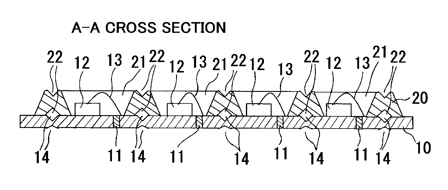
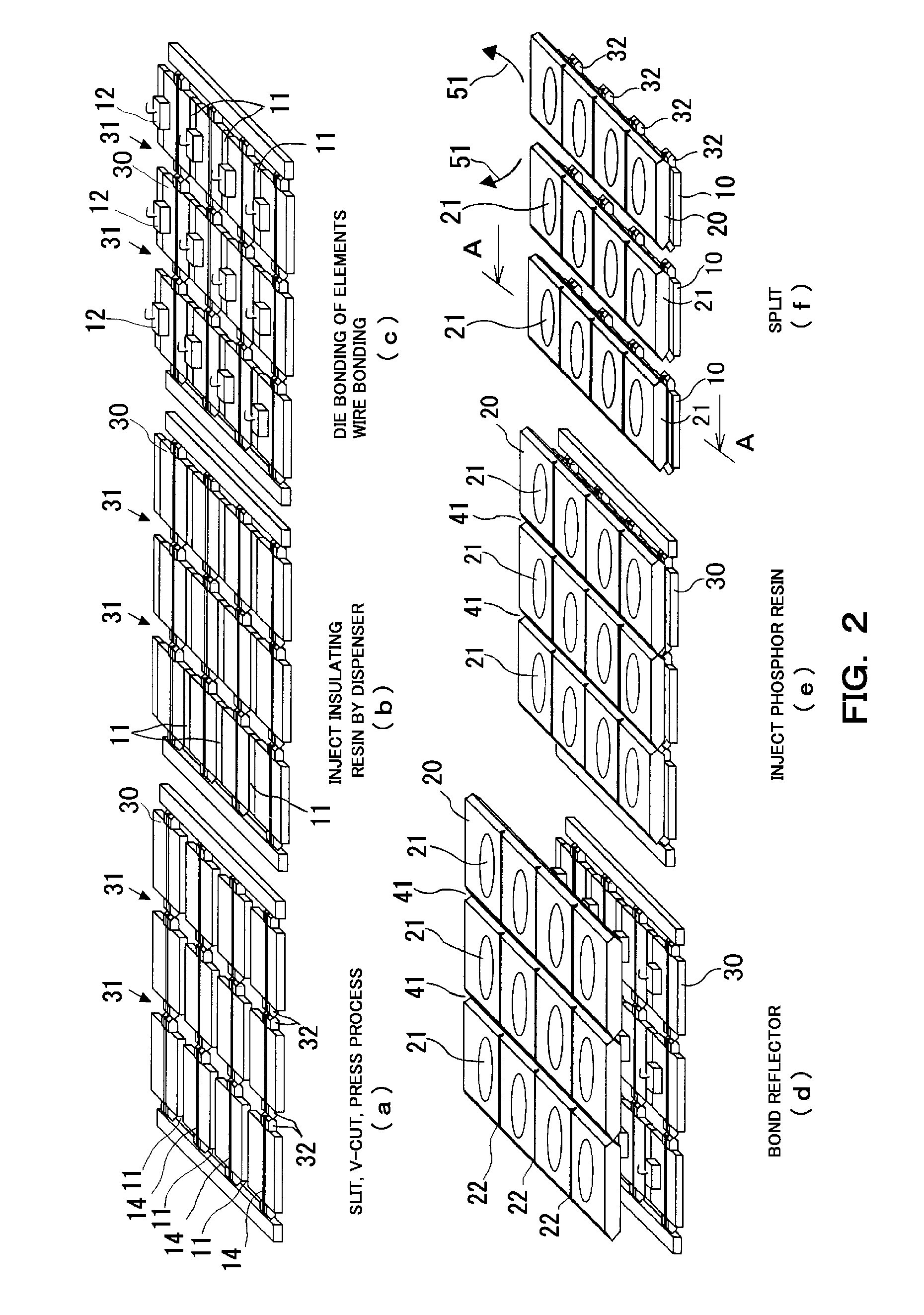
[0032]As illustrated by the sectional view of FIG. 1 and the perspective view of FIG. 2(f), the line-shaped light emitting apparatus incorporates a mounting plate 10 made of metal, four LED elements 12 mounted in a line in the longitudinal direction of the mounting plate 10, and a plate-like reflector 20 made of resin mounted in such a manner as superimposed on the mounting plate 10. The plate-like reflector 20 is provided with four apertures 21 each being a mortar shape and the reflector is mounted on the mounting plate 10 in such a manner that the LED elements 12 are positioned respectively in the apertures 21 at the center thereof.

[0033]As illustrated by the top view of the mounting plate 10 in FIG. 3, the mounting plate 10 made of metal is provided with four insulating slits 11 which are orthogonal to the longitudinal direction of the mounting plate 10, respectively...

second embodiment

[0058]Next, the second embodiment of the present invention will be explained.

[0059]The first embodiment is directed to a procedure that the insulating adhesive is injected into the insulating slit 11 by the dispensing method in the step shown in FIG. 2(b), and the adhesive agent is coated on the surface of the metal plate 30 in the step shown in FIG. 2(d), so as to bond the reflector 20 thereon. In the second embodiment, the step of FIG. 2(b) and the step of FIG. 2(d) are integrated to one step.

[0060]Specifically, as shown in FIG. 7(b), before the dispensing step, steps for die bonding of the LED element 12 and bonding of the wire 13 are performed. Thereafter, in the dispensing step, when the insulating adhesive is injected into the insulating slit 11 by a dispenser, injection volume is increased, thereby allowing the adhesive agent to overflow from the insulating slit 11 onto the top surface of the metal plate 30. Accordingly, as shown in FIG. 8, it is possible to form an adhesive ...

third embodiment

[0063]In the first embodiment, the LED element 12 is die-bonded by using the adhesive resin, but the method of die bonding is not limited to such usage of the adhesive agent. In the third embodiment, there will be explained a case where die bonding is performed by eutectic bonding.

[0064]When eutectic solder (e.g., AuSn alloy) is used for the die bonding, it is necessary to heat the solder up to 180° C. or higher so as to melt the solder. Therefore, if the die bonding is performed after injecting the insulating adhesive agent into the insulating slit 11, there is a possibility that the heat may cause deterioration (e.g., discoloration or exfoliation of resin). In the third embodiment, die bonding of the LED element 12 is performed before the dispensing step. Firstly, in the step as shown in FIG. 9(b), the die bonding is performed by using the eutectic solder, and thereafter in the step as shown in FIG. 9(c) the insulating adhesive agent is injected into the insulating slit 11. Subseq...


PUM

PropertyMeasurementUnit
residual thicknessaaaaaaaaaa
thicknessaaaaaaaaaa
areaaaaaaaaaaa

Abstract

The present invention provides a method for manufacturing a light emitting apparatus which can be separated by splitting, even though a mounting plate made of metal is employed. A metal plate is prepared, on which at least one joint slit made up of a joint and an opening is formed in a predetermined direction for integrating multiple mounting plates of the light emitting apparatuses. Multiple light emitting elements set in array are mounted on the metal plate. An aperture is provided at a position corresponding to a position for mounting the light emitting element on the metal plate, and a plate-like reflector made of resin, on which a first reflector splitting groove is formed at a position coinciding with the joint slit of the metal plate, is mounted and fixed on the metal plate in such a manner as superimposed thereon. The metal plate and the plate-like reflector being superimposed and fixed one on another are broken along the joint slit of the metal plate and the first reflector splitting groove of the plate-like reflector. The metal plate and the resinous reflector are superimposed one on another and broken together, whereby the metal plate can be split successfully.

Description

[0001]This application claims the priority benefit under 35 U.S.C. §119 of Japanese Patent Application No. 2009-147905 filed on Jun. 22, 2009, which is hereby incorporated in the entirety by reference.FIELD OF THE INVENTION[0002]The present invention relates to a method for manufacturing a light emitting apparatus on which a light emitting diode (LED) is mounted, and more particularly, it relates to a method for manufacturing a light emitting apparatus on which multiple LEDs are mounted in the form of line.DESCRIPTION OF THE RELATED ART[0003]Japanese Unexamined Patent Application Publication No. 2000-58924 (hereinafter, referred to as “patent document 1”) discloses that a thin sheet metal is employed as a mounting plate in order to enhance a heat radiation effect of the mounting plate on which the LED is mounted. The thin sheet metal is separated into two electrode areas according to a slit which is created by a press work, and one of the electrode areas is processed into a concave,...

Claims


Application Information

Patent Timeline
Patent Type & Authority Applications(United States)
IPC IPC(8): F21V7/00F21V21/005B23P11/00
CPCH01L33/486H01L33/60H01L2224/48091H01L24/97H01L2924/07802H01L2924/01322H01L2933/0033Y10T29/49826H01L2924/00014H01L2924/00H01L24/85H01L2224/97H01L2924/12041H01L2224/85
Inventor SAKAI, TAKAAKIKATANO, SHINICHI
Owner STANLEY ELECTRIC CO LTD
Learn More