
System and methods for efficient provision of arc welding power source

a technology of arc welding and power supply, applied in the field of welding power supply, can solve the problems of circuit power loss, circuit power loss, circuit design inefficiency,

Active Publication Date: 2010-12-23
ILLINOIS TOOL WORKS INC
View PDF4 Cites 24 Cited by
  • Summary
  • Abstract
  • Description
  • Claims
  • Application Information

AI Technical Summary

Benefits of technology

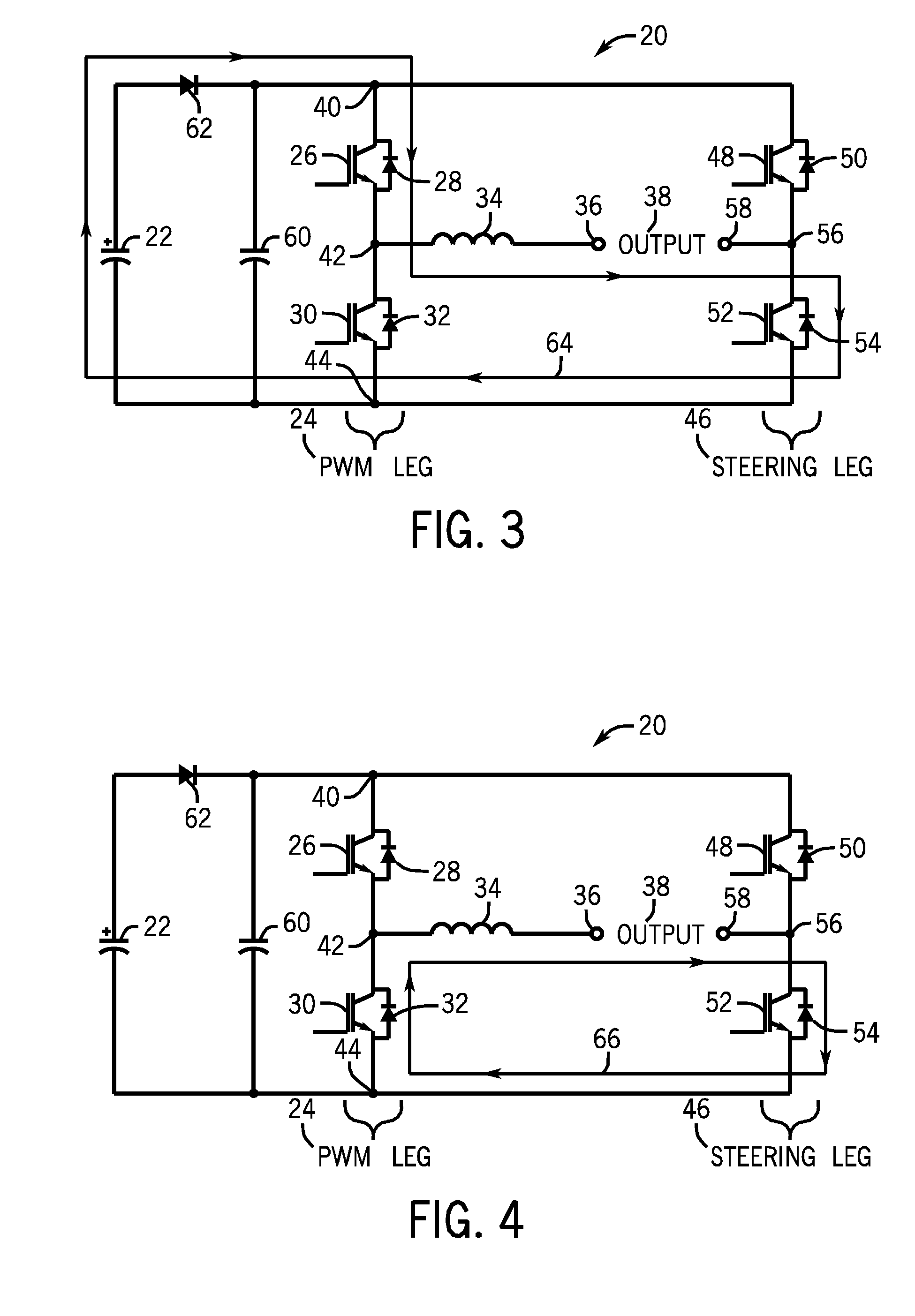
[0004]The present disclosure is directed to systems and methods relating to a power control circuit. One embodiment of the present disclosure efficiently achieves a desired square wave AC output by combining components of a buck converter and a full bridge inverter in a unique manner. In particular, the present disclosure provides methods and systems for creating and controlling an AC output for welding, plasma cutting or heating. For example, one embodiment of the present disclosure provides a power control circuit and current flow paths through the power control circuit that are generated via switching of transistors in the circuit on and off. Specifically, in one embodiment, the power control circuit includes a pulse width modulation leg, which controls the level of current flow through an inductor. Additionally, the power control circuit may include a bidirectional buck converter that converts an unregulated DC flow from a source to a regulated DC flow through the inductor. Further, the power control circuit may include a steering leg, which controls a direction of current flow through the inductor. In some embodiments, an output clamp circuit of the power control circuit may function to suppress the parasitic load inductance during polarity reversal. In other embodiments, if a voltage higher than the input voltage is not required to maintain the arc current during polarity reversal, then the output clamp circuit may be removed and an input leg may be used to suppress the parasitic load inductance during polarity reversal.

Problems solved by technology

Since welding operations generally require high current levels and low voltage levels at the output, an important design criterion of typical welding and plasma cutting power supply circuits is the limitation of power losses in the circuit.
However, it is now recognized that traditional power supply circuits include a combination of components (e.g., buck converter, full bridge inverter, and output clamp circuit) that typically contain multiple transistors and diodes, which greatly contribute to power losses in the circuit, leading to inefficiencies in the circuit design.

Method used


Image

  • System and methods for efficient provision of arc welding power source
  • System and methods for efficient provision of arc welding power source
  • System and methods for efficient provision of arc welding power source

Examples


Embodiment Construction

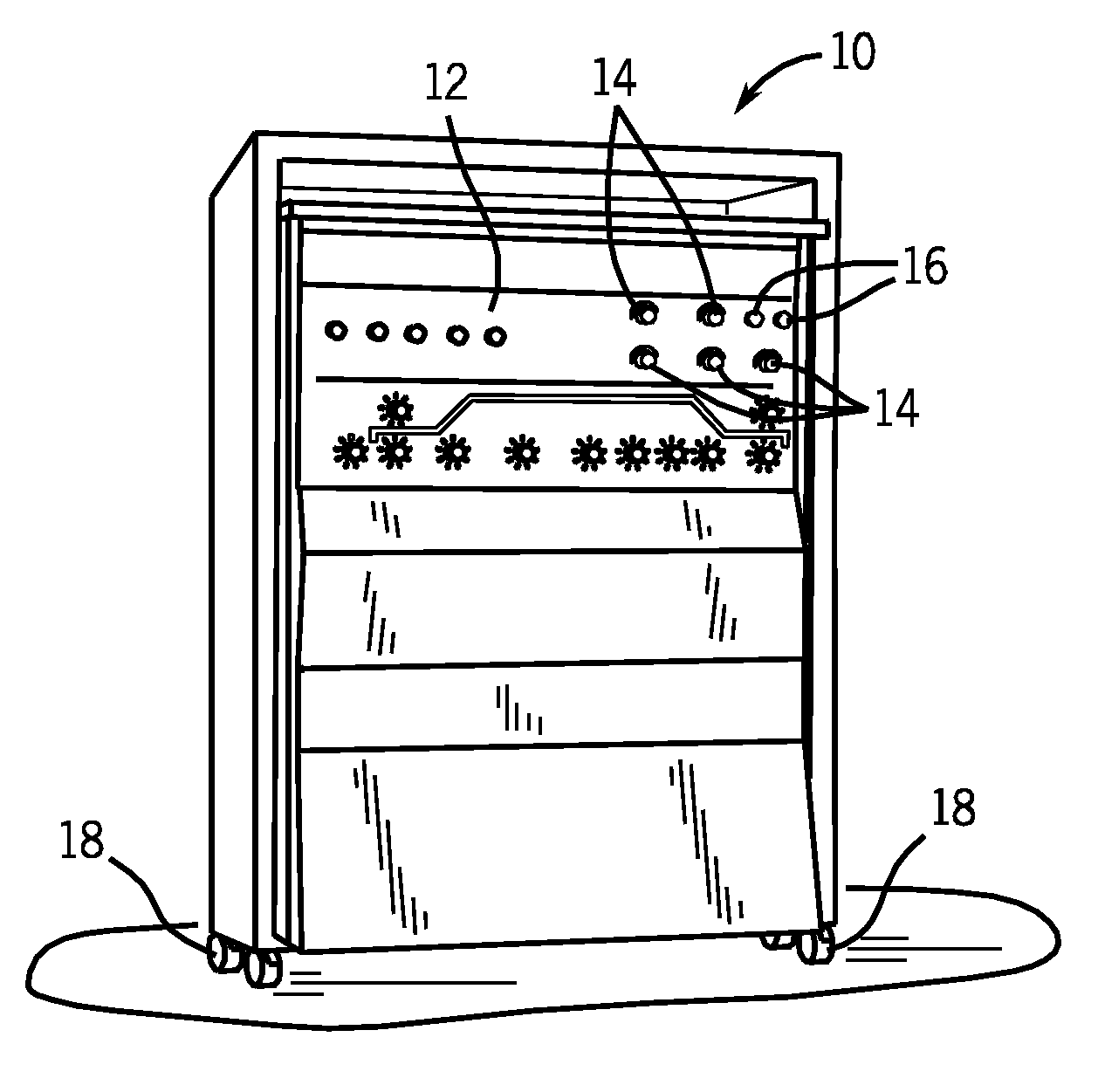
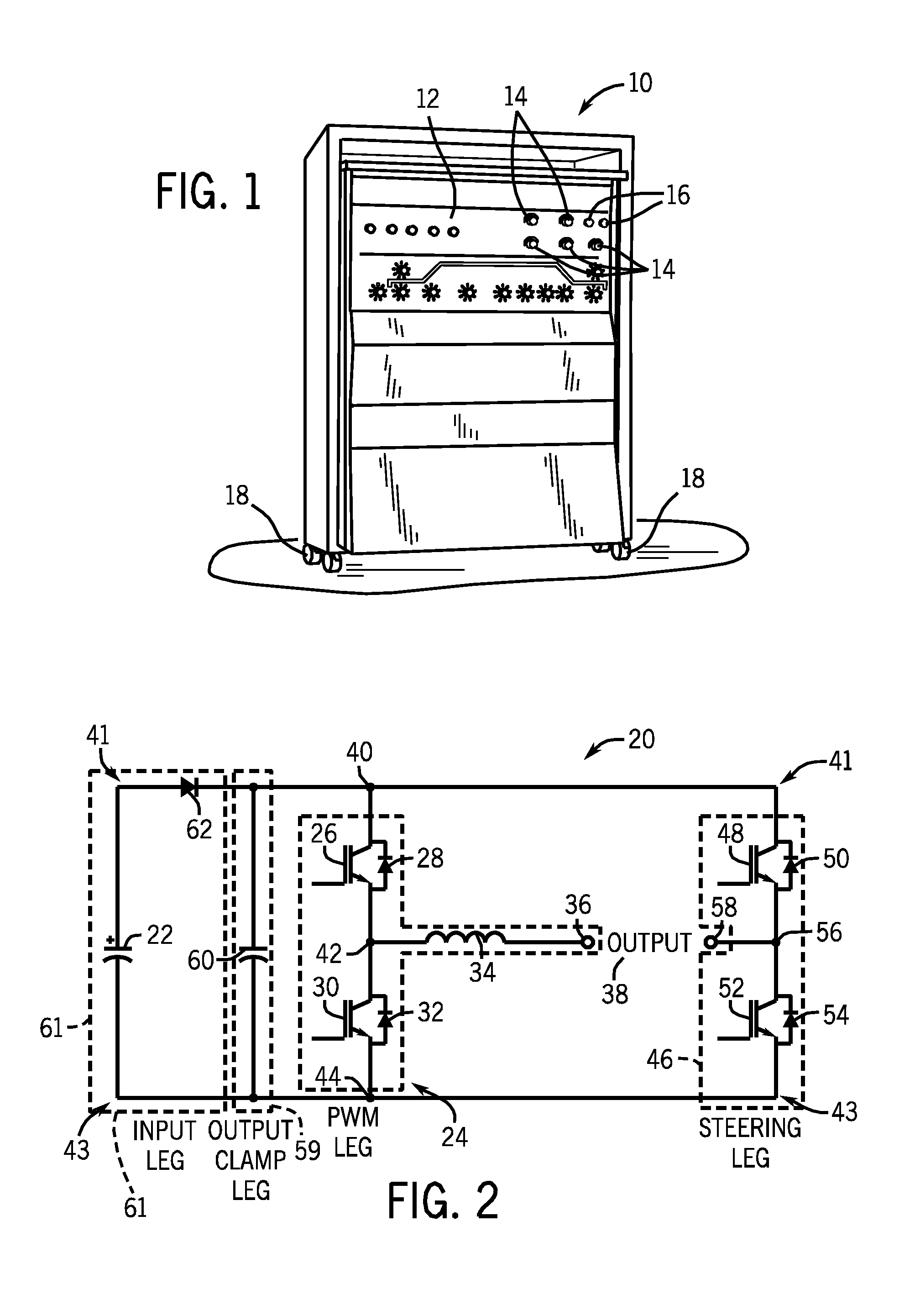
[0018]FIG. 1 illustrates an exemplary welding, cutting or heating power supply 10, which functions to power and control a welding, cutting or heating operation in accordance with aspects of the present disclosure. The power supply unit 10 in the illustrated embodiment contains a control panel 12 through which a user may control the supply of materials, such as power, gas flow, and so forth, to the welding, cutting or heating operation through knobs 14 or other panel components. The power supply 10 contains ports 16, which may communicatively couple the power supply 10 to other system components, such as a torch, a work lead, a wall power outlet, and so forth. The portability of the unit 10 depends on a set of wheels 18, which enable the user to easily move the power supply unit 10 to the location of a workpiece.

[0019]FIG. 2 is a circuit diagram illustrating one embodiment of an output power control circuit 20 of the welding power supply 10 in accordance with aspects of the present d...


PUM

PropertyMeasurementUnit
currentaaaaaaaaaa
output currentaaaaaaaaaa
frequencyaaaaaaaaaa

Abstract

Methods and systems for creating and controlling an AC output for welding, plasma cutting or heating are provided. One embodiment of the present disclosure achieves a desired square wave AC output and reduces the number of circuit components needed by combining components of a buck converter and a full bridge inverter. Current flow paths through a power control circuit that are generated via switching of transistors in the circuit on and off are provided. In one embodiment, a pulse width modulation leg, which controls the level of current flow through an inductor, is provided. Certain embodiments include a bidirectional buck converter that converts an unregulated DC flow to a regulated DC flow through an inductor. In one embodiment, a steering leg is provided, which controls a direction of current flow through the inductor. Additionally, an output clamp circuit, which suppresses the parasitic load inductance during polarity reversal is provided.

Description

BACKGROUND[0001]The present disclosure relates generally to welding power supplies, and more particularly, to systems and methods for controlling current flow through an output load of a power control circuit.[0002]Welding power supply circuits typically convert power from a primary source to an output suitable for welding operations. The output power is provided at an appropriate voltage or current level and may be controlled and regulated according to the process requirements. Some welding processes require the output to be AC. For instance, typical high current AC outputs for gas tungsten arc welding (GTAW) or submerged arc welding (SAW) may require circuitry that efficiently generates a square wave output with a magnitude of several hundreds of amperes. Typical circuit topologies designed to meet this need include a buck converter that steps down a supplied DC voltage, a full bridge inverter that converts the stepped down DC voltage to an AC output, and an output clamp circuit t...

Claims


Application Information

Patent Timeline
Patent Type & Authority Applications(United States)
IPC IPC(8): B23K9/10
CPCB23K9/1043B23K9/1012H02M7/5387B23K9/095
Inventor MADSEN, MICHAEL DAVIDSCHARTNER, QUINN WILLIAM
Owner ILLINOIS TOOL WORKS INC
Learn More