
Leakage Detection System in a Wind Turbine

a leakage detection and wind turbine technology, applied in the direction of engine fuction, engine lubrication, couplings, etc., can solve the problems of high amount of oil already leaked, high amount of oil may leak out of the hydraulic device, etc., and achieve the effect of fast leakage detection

Active Publication Date: 2010-12-23
SIEMENS GAMESA RENEWABLE ENERGY AS
View PDF5 Cites 13 Cited by
  • Summary
  • Abstract
  • Description
  • Claims
  • Application Information

AI Technical Summary

Benefits of technology

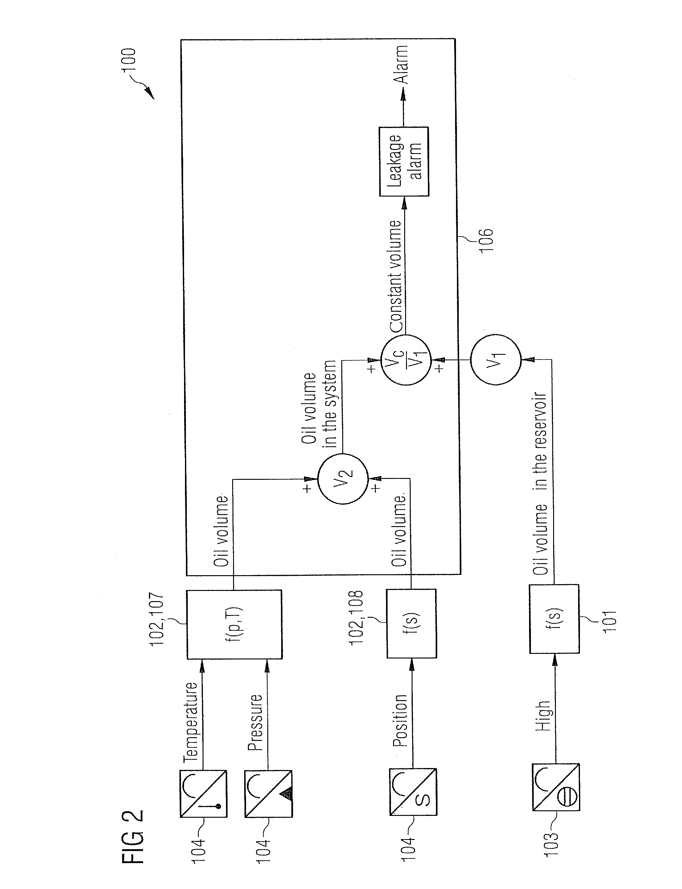
[0021]According to a further exemplary embodiment of the hydraulic system, the controller is adapted for comparing the measured first volume with a predetermined reference value of the first volume. The reference value of the first volume is a function of the at least one parameter. By the present exemplary embodiment, a predetermined reference value may be given to the controller. The predetermined reference value may be indicative of the measured parameters in the hydraulic device. In particular, if the temperature in the hydraulic system is high, the hydraulic fluid in the hydraulic device expands and thus a lower amount of the second volume of the hydraulic fluid circulates in the hydraulic device. That is, that the amount of the first volume of the hydraulic fluid in a regular operating hydraulic system should be higher due to the higher temperature in the hydraulic device, so that a lower amount of second volume of hydraulic fluid is needed in the hydraulic device so that the second volume is lower. In other words, the predetermined reference value of the first volume for a regular operating hydraulic system may be taken for instance from a table in which for each working conditions and for each measured parameters a certain reference value e.g. of the first volume may be predetermined. Thus, the predetermined reference value may be exactly adapted to certain operating status of the hydraulic devices, so that the control range of the level of the first volume in the reservoir for a regularly operating system may be kept very small. In comparison to the conventional hydraulic leakage detecting systems, a predetermined reference value gives the lowest possible level of the first volume in a regularly operating system in order to prevent false alarm. Thus, a more exact control system may be provided.
[0023]According to a further exemplary embodiment of the hydraulic system, the controller is adapted for calculating the predetermined reference value on the basis of a system status of the hydraulic device. The system status may comprise information about all installed (hydraulic) components, the diameters and the length of the hydraulic lines, the waste, the lifetime and the age of the installed components or other circumstances that could influence the consumption of hydraulic fluid in the hydraulic device. For instance, an accumulator or an intermediate tank for the hydraulic fluid located in the hydraulic device may be pre-pressurized by a nitrogen pre-pressure. Thus, due to the amount and the pressure of the nitrogen a certain second volume of the hydraulic fluid may be stored in the intermediate tank. Thus, if the controller measures the amount and the pressure of the nitrogen, a certain amount of second volume of hydraulic fluid is consumed by the hydraulic device in a regular working state. Thus, the predetermined reference value may be adopted and recalculated on the basis of the system status. Moreover, it is known that over a lifetime of a component waste occurs and thus more hydraulic fluid may be used. This could be also an indicator for the system status that may cause the controller to recalculate a predetermined reference value. Moreover, the controller may be aware of the component version installed in the hydraulic device. In particular, if a larger or smaller hydraulic cylinder may be installed, the part number may be inputted to the controller, so that the predetermined reference value may be automatically adapted to the new consumption of the newly installed hydraulic cylinder by the controller. Thus, a very flexible and self-acting hydraulic leakage system may be provided. Complex and time-consuming modulations of the hydraulic system may be prevented.

Problems solved by technology

If a leakage turns up in the hydraulic system, in particular at outside located hydraulic devices with a large distance from to the oil tank, a high amount of oil may leak out from the hydraulic device before the oil level sensor may measure the leakage based on recirculation of the hydraulic fluid.
In the time period between the beginning of the leakage and the alarm initiation a high amount of oil may be already leaked.

Method used


Image

  • Leakage Detection System in a Wind Turbine
  • Leakage Detection System in a Wind Turbine
  • Leakage Detection System in a Wind Turbine

Examples


Embodiment Construction

[0034]The illustrations in the drawings are schematically. It is noted that in different figures, similar or identical elements are provided with the same reference signs.

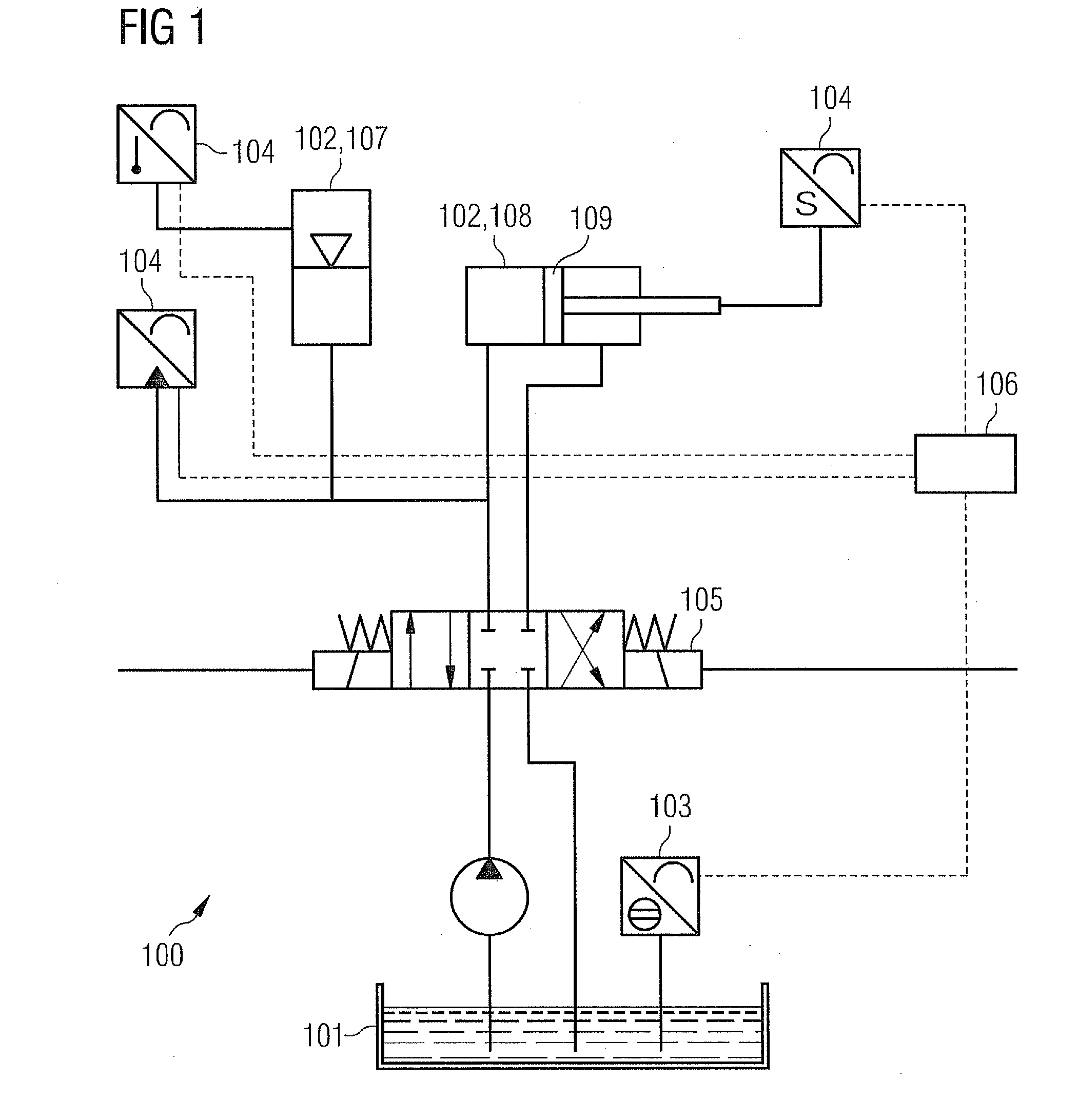
[0035]FIG. 1 illustrates a hydraulic system 100. The hydraulic system 100 comprises a reservoir 101, a hydraulic device 102, a first sensor 103, a second sensor 104 and a controller 106. The reservoir 101 is connected to the hydraulic device 102 for supplying hydraulic fluid to and / or from the hydraulic device 102. The first sensor 103 is adapted for measuring a first volume V1 of the hydraulic fluid in the reservoir 101. The second sensor 104 is connected to the hydraulic device 102 in such a way that at least one parameter being indicative for a second volume V2 of the hydraulic fluid in the hydraulic device 102 is measurable. The controller 106 is adapted for calculating the second volume V2 of the hydraulic fluid based on the at least one parameter. Moreover, the controller 106 is adapted for determining a leak...


PUM


Abstract

In one aspect, a hydraulic system including a reservoir, a hydraulic device, a first sensor, a second sensor and a controller is described. The reservoir is connected to the hydraulic device for supplying hydraulic fluid to and from the hydraulic device. The first sensor is adapted for measuring a first volume of the hydraulic fluid in the reservoir. The second sensor is connected to the hydraulic device such that at least one parameter being indicative for a second volume of the hydraulic fluid in the hydraulic device is measurable. The controller is adapted for calculating the second volume of the hydraulic fluid based on the at least one parameter. The controller is adapted for determining a leakage of hydraulic fluid in the hydraulic system based on the first volume and the second volume.

Description

FIELD OF INVENTION[0001]The present invention relates to a hydraulic system and a wind turbine. Moreover, the invention relates to a method for determining a leakage of a hydraulic fluid in a hydraulic system.ART BACKGROUND[0002]Today, systems in wind turbines for controlling and operating the wind turbine are based on hydraulic systems. In particular, a pitch servo system and a brake system of a wind turbine may be based on hydraulic systems and components.[0003]In the nacelle of the wind turbine a hydraulic fluid tank or a reservoir and a pump station is installed for supplying the hydraulic fluid to the hydraulic devices. The hydraulic fluid, e.g. hydraulic oil, is pumped to the installation locations of the hydraulic systems and hydraulic components. In particular, the hydraulic fluid may be pumped outside of the nacelle of the wind turbine, such as to the outer placed pitch servo system in a hub of the wind turbine. The hydraulic device may provide accumulator banks, proportion...

Claims


Application Information

Patent Timeline
Patent Type & Authority Applications(United States)
IPC IPC(8): F15B21/00
CPCF05B2260/80F15B19/005F15B2211/6306F16N19/003F15B2211/6343F15B2211/665F15B2211/6336Y02E10/72
Inventor EGEDAL, PERMUNCH, JESPER
Owner SIEMENS GAMESA RENEWABLE ENERGY AS
Learn More