
Method and Device for Displaying the Limits of Flight Margins for an Aircraft

a technology for aircraft and limits, applied in the field of aircraft navigation aids, can solve problems such as increasing the risk of being in proximity to obstacles, and achieve the effect of improving safety

Active Publication Date: 2010-12-16
THALES SA
View PDF24 Cites 18 Cited by
  • Summary
  • Abstract
  • Description
  • Claims
  • Application Information

AI Technical Summary

Benefits of technology

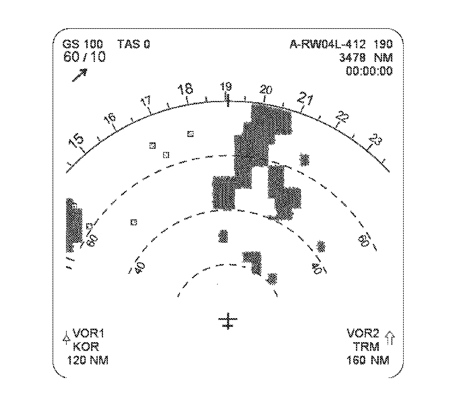
[0009]Embodiments of the present invention advantageously improve safety during situations where the helicopter operates with low lateral and vertical separation margins with respect to the terrain or obstacles situated in proximity, and provide the pilot with a representation of the exterior environment allowing him to anticipate at-risk situations.
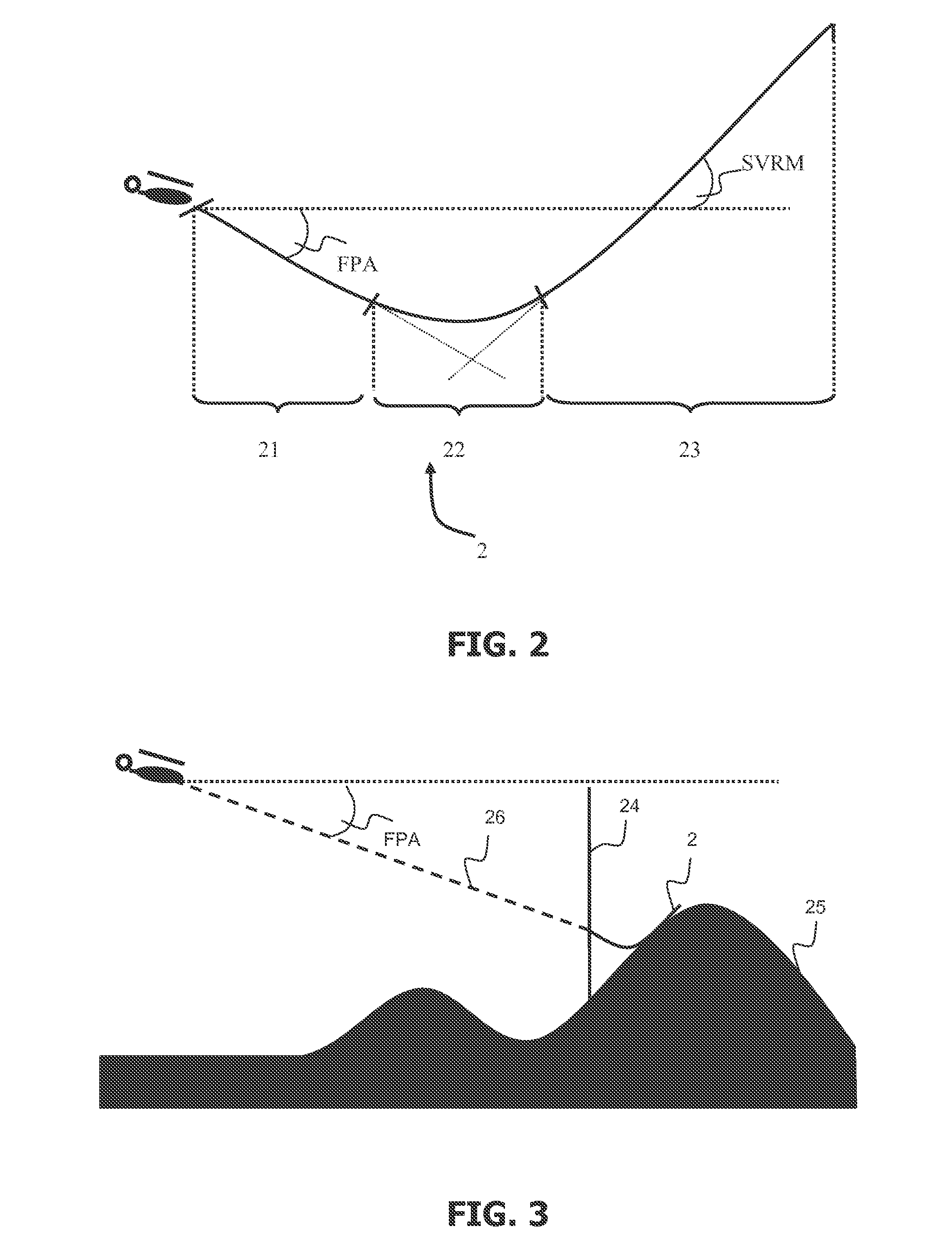
[0017]Advantageously the flight margins are displayed for obstructions located beyond the protection envelope of the aircraft. This allows the pilot to view the zones at risk without however penetrating into a zone for which the aircraft's anti-collision system generates a collision alert. This makes it possible to reduce the stress factor of the pilot and of his crew as well as the surprise effect of triggering an alert. The protection envelope, or prober, is the monitoring volume calculated by the aircraft anti-collision system. It is generally calculated as a function of avoidance maneuvers predefined in the anti-collision system. A method according to this aspect of the invention displays limits of flight margins in relation to obstructions not to be exceeded in order to avoid situations of alerts in the sense of a TAWS.
[0025]Various aspects of the invention make it possible to display the operational limits of margins in the zones far from the trajectory of the aircraft and to maintain the display of the collision alert zones for the positions around the trajectory. The function of the operational margins is to present the positions allowing the aircraft to carry out a flattening out phase for a predetermined duration. This is the maneuver generally carried out while the pilot gets his bearings in a zone not initially envisaged.

Problems solved by technology

The urgent nature of the mission and the taking of risks which stems therefrom, correspondingly increase the risks of being in proximity to obstacles.

Method used


Image

  • Method and Device for Displaying the Limits of Flight Margins for an Aircraft
  • Method and Device for Displaying the Limits of Flight Margins for an Aircraft
  • Method and Device for Displaying the Limits of Flight Margins for an Aircraft

Examples


Embodiment Construction

[0032]The anti-collision monitoring system makes it possible to achieve the objectives aimed at by making the following systems collaborate.

[0033]A system of databases making it possible to have available data regarding location and the altitude of the surrounding obstacles, terrain data, flight parameter data specific to the aircraft (maximum climb capability, flight envelope, flight margins, etc.) and data relating to flight maneuvers, notably avoidance maneuvers.

[0034]A system of TAWS type carrying out the trajectory monitoring functions in relation to the terrain and making it possible to raise ad hoc alerts in the event of coming dangerously close to the relief and obstacles.

[0035]The avionics systems transmitting the aircraft's flight parameters in real time (heading, roll rate, altitude, position, etc.)

[0036]A system of display devices in the cockpit making it possible to present the information formulated by the monitoring system.

[0037]Preferably, the functions for carrying ...


PUM


Abstract

A method of displaying, for a system for anti-collision monitoring of an aircraft, the limits of flight margins in relation to obstructions located in a flight zone, and a device for displaying the limits of operational flight margins and the limits of alert zones, is provided. The operational flight margins in the flight zones not initially envisaged, and the limits of the alert zones around the trajectory of the aircraft, are presented.

Description

CROSS-REFERENCE TO RELATED APPLICATIONS[0001]This application claims priority to foreign Patent Application FR 09 02874, filed on Jun. 12, 2009, the disclosure of which is incorporated herein by reference in its entirety.FIELD OF THE INVENTION[0002]The invention relates to the field of aerial navigation aids for the prevention of accidents in which a still-maneuverable aircraft collides with an obstacle. The term “obstacle” subsequently designates any non-natural obstruction present in the environment of the aircraft, one then speaks notably of human constructions such as buildings or bridges. Moreover, the term “relief” or “terrain” designates obstructions relating to the natural environment such as mountainous zones.BACKGROUND OF THE INVENTION[0003]Owing to the type of missions carried out, landing and takeoff in zones that are difficult to access, sometimes unprepared, or flight at low altitude, a helicopter, for example, is a craft which is very highly exposed to the risk of col...

Claims


Application Information

Patent Timeline
Patent Type & Authority Applications(United States)
IPC IPC(8): G08G5/04G08B23/00
CPCG08G5/0021G08G5/045G08G5/0086
Inventor FLOTTE, LAURENTMARTY, NICOLASLAURENT, ERIC
Owner THALES SA
Learn More