Light source arrangement for an illumination device of a medical-optical observation

a technology of optical observation and illumination device, which is applied in the field of light source arrangement of illumination device of medical optical observation apparatus, can solve the problems of not being able to easily replace the optical components of existing illumination device, the illumination device is more bulky, and the more complex optical unit can be used preferably, so as to achieve the effect of reducing the size of the luminescence emitter, reducing the cost of operation, and ensuring the quality of the imag

Active Publication Date: 2010-12-09
CARL ZEISS MEDITEC AG
View PDF14 Cites 3 Cited by
  • Summary
  • Abstract
  • Description
  • Claims
  • Application Information

AI Technical Summary

Benefits of technology

[0010]A double collector can advantageously be employed as the imaging optical unit. Such a double collector affords the possibility that a parallel beam path is present between the two lenses of the double collector. In this way, the image of the at least one luminescence emitter can be generated at any desired distance from the luminescence emitter. With the use of light-directing elements such as, for instance, mirrors or prisms, great freedom then arises in the positioning of the at least one luminescence emitter. The latter can therefore also be arranged at a greater distance from the illumination device. Moreover, a total of at least four lens surfaces are then available, which can be chosen in a suitable manner for producing an optimized imaging quality.
[0011]In one development of the invention, the imaging optical unit of the light source arrangement has at least one aspherical lens, which can be advantageous with regard to the correction of imaging aberrations, particularly with regard to the correction of a spherical aberration. Moreover, the imaging optical unit can comprise an achromatic or apochromatic lens in order that chromatic aberrations in the imaging of the luminescence emitter are kept small. This is advantageous, in particular, if a luminescence emitter that emits broadband light such as, for instance, a white light emitting diode is employed. Instead of a luminescence emitter that emits broadband light, however, it is also possible to employ a luminescence emitter that emits narrowband light, for example if illumination in a narrow spectral range is intended to be effected. However, a luminescence emitter that emits narrowband light can also be employed if the illumination of an observation object with broadband light is intended to be effected. In this case, the light source arrangement comprises a converter element, that is to say an independent part not integrated into the luminescence emitter, which converter element is provided with a converter phosphor for converting at least part of the narrowband light of the luminescence emitter. In that case the converter element is introduced or can be introduced into the light source arrangement between the at least one luminescence emitter and the image of the at least one luminescence emitter, for example between the imaging optical unit and the image of the at least one luminescence emitter. In such a configuration of the light source arrangement, by exchanging the converter element for a converter element having a different converter phosphor, it is possible to alter the spectral characteristic of the image of the light source, for example in order to provide light having a specific color temperature.
[0012]The converter element can have an entrance surface for the light emerging from the luminescence emitter, which entrance surface faces the luminescence emitter and is provided with a dichroic layer that is transparent to light entering into the converter element and having the wavelength distribution of the light emitted by the luminescence emitter. By contrast, said dichroic layer is highly reflective to converted light directed in the direction of the luminescence emitter. In this way, it is possible to prevent converted light from emerging from the converter element in the direction of the luminescence emitter and thus being lost for the illumination.
[0013]An illumination device according to the invention for a medical-optical observation apparatus is equipped with at least one light source arrangement according to the invention. The use of a light source arrangement according to the invention with a luminescence emitter, for instance an LED, as primary light source affords a considerable price advantage, and additionally a longer service life, compared with the use of halogen and xenon lamps. In comparison with the use of an optical fiber as a light source, light emitting diodes, in particular, afford the advantage of more homogeneous light propagation.

Problems solved by technology

However, more complex optical units can preferably be used as well.
Such enlargement means more structural space, however, which would make the illumination device more bulky.
Moreover, it is not readily possible to replace the optical components in existing illumination devices.

Method used


Image

  • Light source arrangement for an illumination device of a medical-optical observation
  • Light source arrangement for an illumination device of a medical-optical observation
  • Light source arrangement for an illumination device of a medical-optical observation

Examples


Embodiment Construction

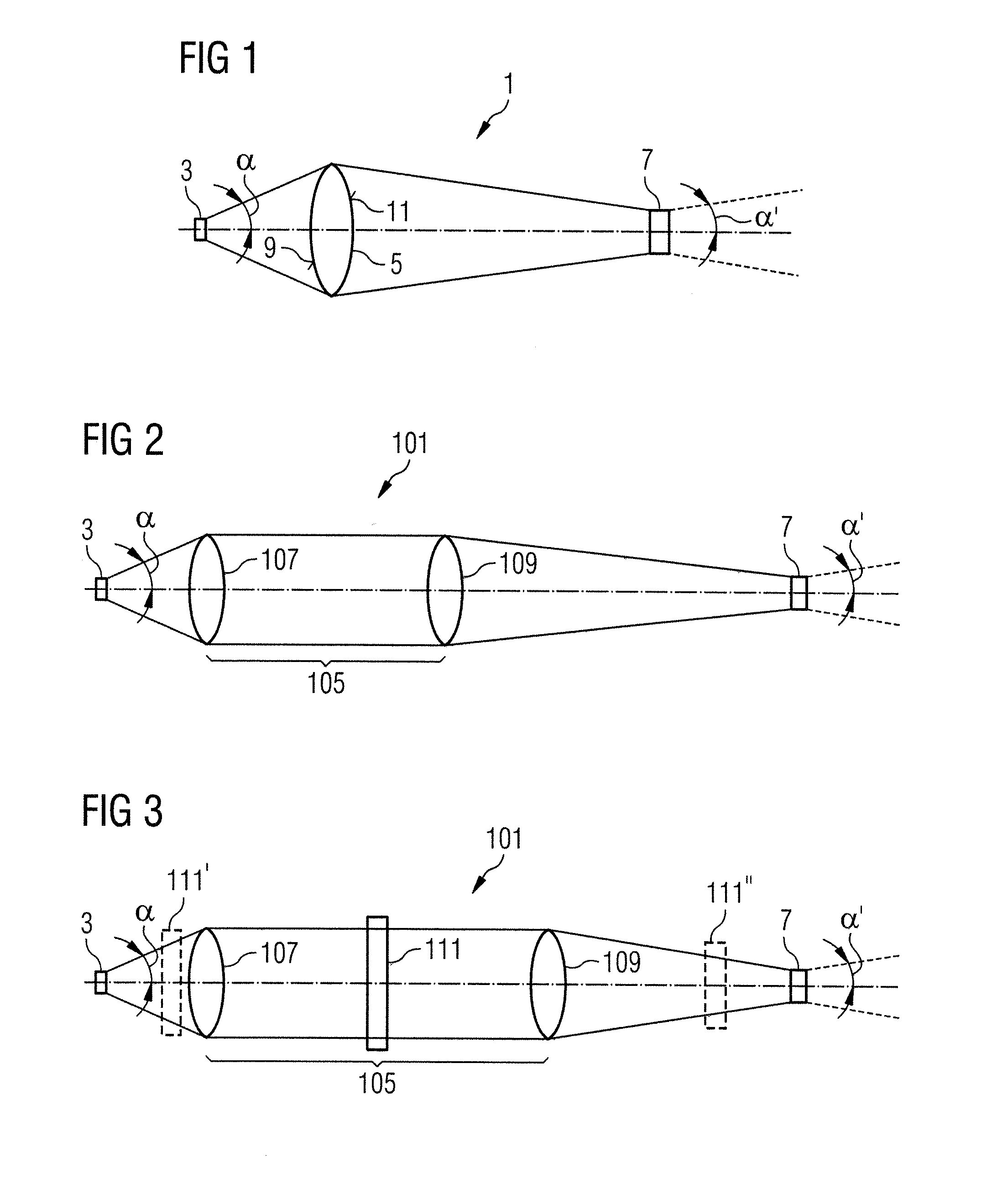
[0023]A first exemplary embodiment of a light source arrangement according to the invention is described below with reference to FIG. 1. The figure shows the simplest construction of the light source arrangement 1 according to the invention, comprising merely a luminescence emitter, a light emitting diode 3 in the present exemplary embodiment, as primary light source and a converging lens 5. The converging lens 5 constitutes the imaging optical unit of the light source arrangement, with the aid of which a real image 7 of the light emitting diode 3 is generated. The optical parameters of the converging lens 5, that is to say its refractive index and the curvatures of the lens surfaces are chosen such that the magnification scale of the image 7 in comparison with the light emitting diode 3 as the original image lies between 1.5 and 2.5, and in particular between 2 and 2.5. This has the effect that the luminous area of the image 7 is 1.5 times to 2.5 times as large as the luminous area...


PUM


Abstract

A light source arrangement (101) for an illumination device of a medical-optical observation apparatus has an illumination light source (7) and an illumination optical unit (15) for illuminating an observation object (23) with illumination light from the illumination light source (7). The light source arrangement (101) has at least one luminescence emitter (3) as light source and an imaging optical unit (105) that generates an image (7) of the at least one luminescence emitter (3) with a defined magnification scale, which image forms the illumination light source for the illumination device.

Description

BACKGROUND OF THE INVENTION[0001]1. Field of the Invention[0002]The present invention relates to a light source arrangement for an illumination device of a medical-optical observation apparatus, which illumination device has an illumination light source and an illumination optical unit for illuminating an observation object with illumination light from the illumination light source. The invention additionally relates to an illumination device for a medical-optical observation apparatus, and such a medical-optical observation apparatus.[0003]2. Description of the Related Art[0004]An illumination device for a surgical microscope, embodied as an ophthalmological surgical microscope, is described for example in DE 10 2007 041 003 A1, wherein the illumination systems in the surgical microscope are supplied from a halogen or xenon light source via spliced optical waveguides. This means, however, that the illumination types of coaxial illumination and surrounding illumination cannot be reg...

Claims


Application Information

Patent Timeline
Patent Type & Authority Applications(United States)
IPC IPC(8): G02B21/06
CPCA61B1/06A61B2019/521G02B21/22G02B21/025G02B21/082G02B21/0012A61B2090/309
Inventor LUECKE, CHRISTIANBAUSEWEIN, MARKUSREIMER, PETER
Owner CARL ZEISS MEDITEC AG
Why Eureka
Try Eureka