
Magnetic sensor device

a technology of magnetic sensor and sensor, which is applied in the direction of measurement devices, magnetic measurements, instruments, etc., can solve the problems of variable field intensity and minute output voltage of magnetoelectric conversion elements, and achieve high precision, simple circuit configuration, and high precision

Active Publication Date: 2010-12-09
ABLIC INC
View PDF2 Cites 8 Cited by
  • Summary
  • Abstract
  • Description
  • Claims
  • Application Information

AI Technical Summary

Benefits of technology

[0010]In view of the above-mentioned circumstances, an object of the present invention is to provide a magnetic sensor device which may remove effects of an element offset voltage and an input offset voltages of an amplifier and a comparator with a relatively simple circuit configuration so as to detect a magnetic field intensity with high precision.
[0013]According to the magnetic sensor device of the present invention, the offset component generated in the magnetoelectric conversion element, the differential amplifier, and the comparator in the magnetic sensor device may be removed with a simple circuit configuration effectively utilizing the switch and the capacitor. Also, a detection voltage level of the magnetic field intensity may be set with high precision. Accordingly, the present invention may provide the magnetic sensor device capable of detecting the magnetic field intensity with high precision.

Problems solved by technology

The output voltage of the magnetoelectric conversion element is minute, and is easily affected by an offset voltage (element offset voltage) of the magnetoelectric conversion element, an offset voltage (input offset voltage) of the amplifier or the comparator, or noise within the conversion device, which leads to a problem.
The noise is mainly generated by a flicker noise of a monolithic transistor that configures a circuit, or a thermal noise of the monolithic transistor or a resistive element.
However, the above-mentioned magnetic sensor device according to the related art suffers from such a problem that the input offset voltage of the comparator 4 connected to a subsequent stage may not be removed, and the detected magnetic field intensity is varied.

Method used


Image

  • Magnetic sensor device
  • Magnetic sensor device
  • Magnetic sensor device

Examples


Embodiment Construction

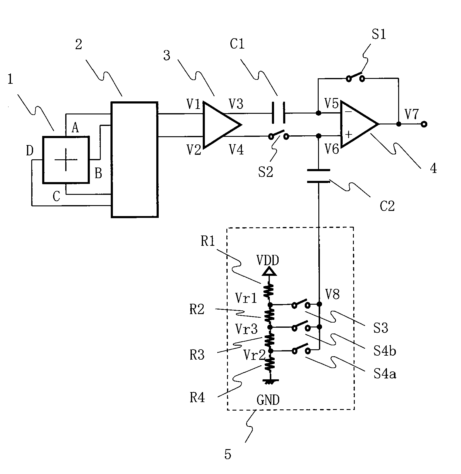
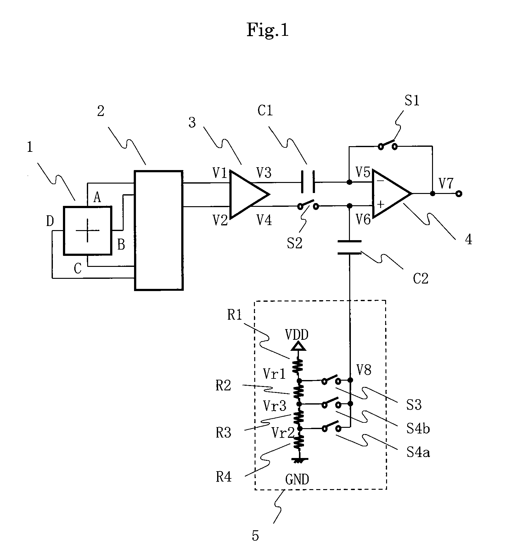
[0022]An embodiment of the present invention is described below in detail with reference to the accompanying drawings. A magnetic sensor device according to the present invention is widely used as a sensor for detecting a state of a magnetic field intensity, such as a sensor for detecting an open / close state in a flip phone or a notebook computer, or a sensor for detecting a rotational position of a motor. In the following embodiment, a magnetic sensor device using a magnetoelectric conversion element is described. A conversion device according to the present invention may employ a conversion element that similarly outputs a voltage according to acceleration or a pressure, in place of the magnetoelectric conversion element that outputs a voltage according to the magnetic field intensity.

[0023]FIG. 1 is a circuit diagram of the magnetic sensor device according to the present invention. The magnetic sensor device according to the present invention includes a Hall element 1 that is a m...


PUM


Abstract

Provided is a magnetic sensor device including: a switching circuit that controls switching of a terminal pair of the magnetoelectric conversion element to which a supply voltage is applied and a terminal pair to which detection voltage of a magnetic intensity is output; a differential amplifier that differentially amplifies the detection voltage; a first capacitor connected to a first output terminal of the differential amplifier; a second switch connected to a second output terminal of the differential amplifier; a comparator that has a first input terminal connected to the first capacitor and a second input terminal connected to the second switch; a first switch connected between the first input terminal and an output terminal of the comparator; and a second capacitor connected to the second input terminal of the comparator; and a detection voltage setting circuit connected to the second capacitor, in which effects of respective offset voltages of the magnetoelectric conversion element, the amplifier, and the comparator are suppressed, and an arbitrary detection magnetic field intensity is set to enable accurate magnetic reading.

Description

RELATED APPLICATIONS[0001]This application claims priority under 35 U.S.C. §119 to Japanese Patent Application No. 2009-137667 filed on Jun. 8, 2009, the entire content of which is hereby incorporated by reference.BACKGROUND OF THE INVENTION[0002]1. Field of the Invention[0003]The present invention relates to a magnetic sensor device for converting a magnetic field intensity into an electric signal, and more particularly to a magnetic sensor device to be employed as a sensor for detecting an open / close state used in a flip phone, a notebook computer, or the like, or a sensor for detecting a rotational position of a motor.[0004]2. Description of the Related Art[0005]A magnetic sensor device has been employed as a sensor for detecting the open / close state used in a flip phone, a notebook computer, or the like, or a sensor for detecting a rotational position of a motor (for example, refer to Japanese Patent Application Laid-open No. 2001-337147). A circuit diagram of the magnetic senso...

Claims


Application Information

Patent Timeline
IPC IPC(8): G01R33/02
CPCG01R33/0029
Inventor MURAOKA, DAISUKEARIYAMA, MINORUHIKICHI, TOMOKIFUJIMURA, MANABU
Owner ABLIC INC
Learn More