Rapid compressor cycling

a compressor and speed technology, applied in the direction of refrigeration safety arrangement, refrigeration components, light and heating equipment, etc., can solve the problem of not allowing the refrigerant system to respond to the effect of cycling

Inactive Publication Date: 2010-12-09
CARRIER CORP
View PDF30 Cites 9 Cited by
  • Summary
  • Abstract
  • Description
  • Claims
  • Application Information

AI Technical Summary

Problems solved by technology

The compressor is cycled in a rapid fashion such that the relatively large thermal inertia of the refrigerant system would not allow the refrigerant system to respond in a timely fashion to changes introduced by refrigerant mass flow variations as compressor alternates between ON to OFF positions.

Method used


Image

  • Rapid compressor cycling
  • Rapid compressor cycling
  • Rapid compressor cycling

Examples


Embodiment Construction

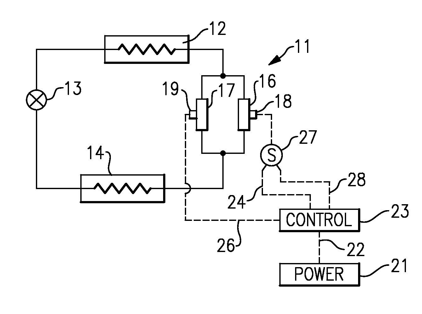
[0015]Shown in FIG. 1 is a basic vapor compression system which includes a compressor assembly 11 a heat rejection heat exchanger (a condenser or a gas cooler) 12, an expansion device 13 and an evaporator 14. In a conventional manner, the refrigerant vapor is compressed in the compressor assembly after which it passes to the heat rejection heat exchanger 12 where the heat is transferred from the refrigerant to a secondary loop fluid such as air, water or glycol. The refrigerant is expanded in the expansion device 13, and the expanded refrigerant that is at lower pressure and temperature then passes to the evaporator 14 where it assimilates heat from an environment, with the resultant refrigerant vapor then passing back to the compressor assembly 11.

[0016]The compressor assembly 11 as shown comprises a pair of compressors 16 and 17 operating in parallel or a so-called tandem configuration. In this regard, it should be understood that the present invention is equally applicable to use...


PUM


Abstract

A single speed compressor is provided with a switching device and control for turning the compressor drive motor ON and OFF in repeated succession at a selected ON time / OFF time ratio within a selected cycle time interval. The ON / OFF ratio and cycle time interval are selected to maintain desired temperature and / or humidity control within a conditioned space.

Description

TECHNICAL FIELD[0001]This invention relates generally to rapid cycling of single speed compressors, and more particularly, to a precise control of temperature and humidity in a conditioned space by utilizing such rapidly cycled single speed compressors.BACKGROUND OF THE INVENTION[0002]During operation of air conditioning and refrigeration systems, it is desirable to vary the capacity of the compressor in an effort to match thermal load demands in a climate-controlled space to provide tight temperature and / or humidity control. This is frequently done by way of a variable speed drive (VSD) which controls the supply voltage and frequency by utilizing an inverter. While a variable speed drive permits continuously varying compressor speed, which in turn allows for a continuous adjustment of the capacity delivered by the variable speed compressor, thereby giving the advantage of smooth operation and better part-load performance, it is relatively expensive. The cost of variable speed drive...

Claims


Application Information

Patent Timeline
Patent Type & Authority Applications(United States)
IPC IPC(8): F25B1/00F25B1/10F25B39/04F25B49/02
CPCF25B49/022F25B2400/075Y02B30/743F25B2600/111F25B2600/112F25B2600/0251Y02B30/70
Inventor LIFSON, ALEXANDERTARAS, MICHAEL F.
Owner CARRIER CORP
Why Eureka
Try Eureka