Amplifying device

a technology of amplifiers and diaphragms, applied in the direction of single-ended push-pull amplifiers, emergency protective circuit arrangements, gain control, etc., can solve the problems of change in capacitance, ecm becomes late, and the potential between the diaphragm and the electrode changes, so as to reduce the manufacturing lead time and cost

Inactive Publication Date: 2010-11-25
PANASONIC CORP
View PDF7 Cites 8 Cited by
  • Summary
  • Abstract
  • Description
  • Claims
  • Application Information

AI Technical Summary

Benefits of technology

[0049]According to an amplifying device according to the invention, input impedance can be set at several GΩ to several tens of GΩ, so that desired electrical characteristics are satisfied and an ESD withstand current rating is improved and thereby, the need for special handling or management in manufacturing is eliminated, so that manufacturing lead time and cost can be reduced.

Problems solved by technology

By this configuration, a displacement of the diaphragm by a sound pressure results in a change in capacitance between the diaphragm and the electrode and results in a change in potential between the diaphragm and the electrode.
On the other hand, when the input impedance is too high, a problem that response time returning to a desired DC operating voltage after detecting a loud voice or turning on a power source of the ECM becomes late arises, so that the input impedance is generally set at about several GΩ to several tens of GΩ.

Method used


Image

  • Amplifying device
  • Amplifying device
  • Amplifying device

Examples


Embodiment Construction

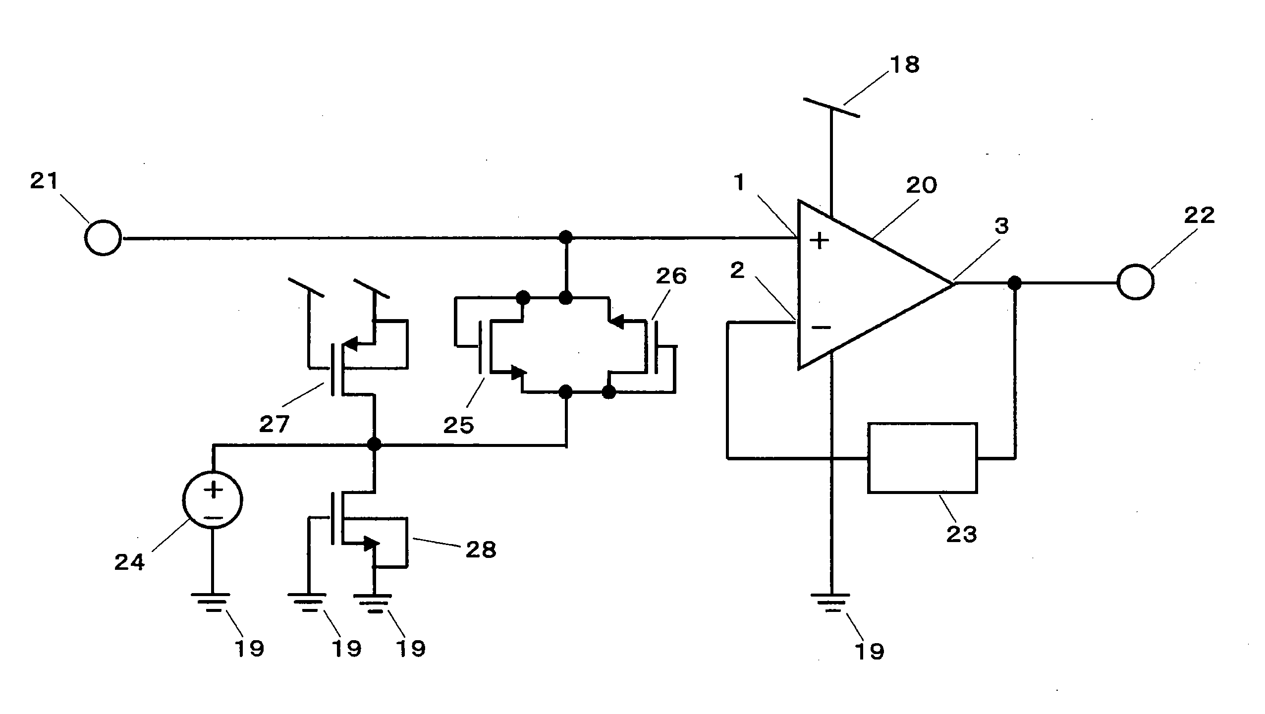
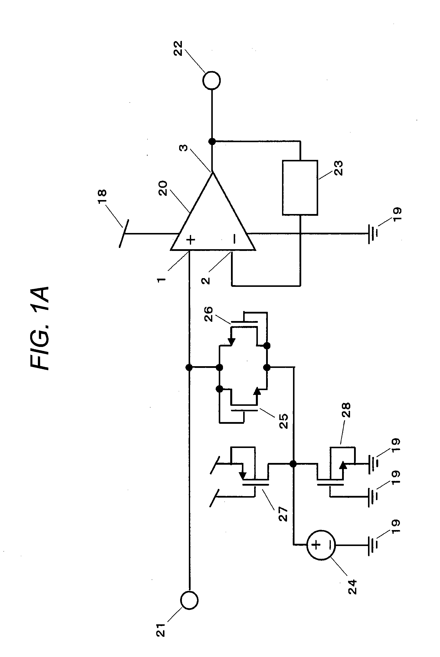
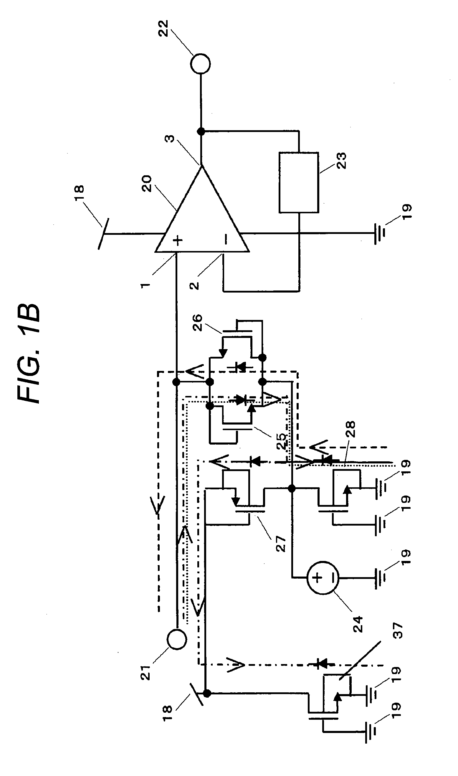
[0104]Next, amplifying devices in examples of the invention will be described in detail with reference to the drawings. FIG. 1A is a diagram describing an amplifying device (1) according to an embodiment of the invention. In addition, the same numerals are assigned to the means having the same action and effect as those described in FIGS. 11 to 12, and the detailed description is omitted.

[0105]In a configuration of FIG. 1A, 27 is a fifth P-channel MOS transistor, and 28 is a seventh N-channel MOS transistor. In the configuration of FIG. 1A, input impedance is set at several GΩ to several tens of GΩ by using a fifth N-channel MOS transistor 25 and a sixth N-channel MOS transistor 26 in a sub-threshold region.

[0106]An ECM is connected to an input terminal 21 and frequency characteristics become flat to a voice band by high input impedance of a CMOS amplifier and the input impedance is set at several GΩ to several tens of GΩ and thereby, response time after detecting a loud voice or tu...


PUM


Abstract

An amplifying device for setting input impedance at several GΩ to several tens of GΩ and improving an ESD withstand current rating is provided.An ECM is connected to an input terminal 21 and frequency characteristics become flat to a voice band by high input impedance of a CMOS amplifier 20 and the input impedance is set at several GΩ to several tens of GΩ and thereby, response time after detecting a loud voice or turning on a power source of the ECM is speeded up and desired electrical characteristics are achieved. A path for releasing a surge voltage which occurs during assembly in the outside of an IC and intrudes from the input terminal 21 to a power source terminal or an earth terminal without an influence on a signal (20 Hz to 20 kHz) of a voice band entering from the input terminal 21 can be constructed by connecting a P-channel MOS transistor 27 and an N-channel MOS transistor 28 as an ESD protective element.

Description

TECHNICAL FIELD[0001]The present invention relates to an amplifying device comprising an ESD (Electrostatic Discharge) protective element or an ESD protective device, and particularly to an amplifying device connected to a signal source with high internal impedance.BACKGROUND ART[0002]An amplifying device connected to a signal source with high internal impedance is commonly used in the field of using a capacitive signal source such as a sound pressure sensor. A typical example of the sound pressure sensor includes a microphone, and a conventional art will be described by taking an electret condenser microphone (hereinafter called an ECM) as an example herein.[0003]The ECM has been commonly used in a small portable device such as a mobile telephone. The condenser microphone is configured to oppose a diaphragm to an electrode and apply a voltage to the electrode from the outside and charge the electrode. By this configuration, a displacement of the diaphragm by a sound pressure result...

Claims


Application Information

Patent Timeline
Patent Type & Authority Applications(United States)
IPC IPC(8): H03F1/52
CPCH03F1/52H03F1/56H03F2203/45576H03F2203/45136H03F3/45475
Inventor FUJITA, NORIYUKIMASAI, SHIGEOSATO, MASAHARU
Owner PANASONIC CORP
Why Eureka
Try Eureka