
Architecture for automotive electrical body systems

Active Publication Date: 2010-11-25
ROBERT BOSCH GMBH
View PDF7 Cites 27 Cited by
  • Summary
  • Abstract
  • Description
  • Claims
  • Application Information

AI Technical Summary

Benefits of technology

[0017]An advantage of the present invention is that the architecture provides superior flexibility, scalability, cost efficiency, and expandability.
[0018]Another advantage is that the wireless architecture is simpler than known wired architectures.
[0019]Yet another advantage is that, for the body domain systems, only a single communication system is used, which reduces the hierarchical problems of known systems.

Problems solved by technology

In order to connect the peripherals, a large number of cables may be necessary, which increases the complexity of the cable harness, increases the weight of the car, and increases the costs of the car.
The increase in the number of cables may also lead to reliability problems in areas where the cable harness is mounted on moveable parts such as the side mirror, doors, seat, etc.
A problem associated with the architecture of FIG. 1 is that it has poor reliability.
For example, if one of the ECUs fails, then the entire associated subsystem is no longer able to operate.
Another problem is that there may be long time delays for end-to-end communication as gateways become bottlenecks.
Yet another problem is that modularity and scalability are limited by the underlying sub-network systems.

Method used


Image

  • Architecture for automotive electrical body systems
  • Architecture for automotive electrical body systems
  • Architecture for automotive electrical body systems

Examples


Embodiment Construction

[0035]The embodiments hereinafter disclosed are not intended to be exhaustive or limit the invention to the precise forms disclosed in the following description. Rather the embodiments are chosen and described so that others skilled in the art may utilize its teachings.

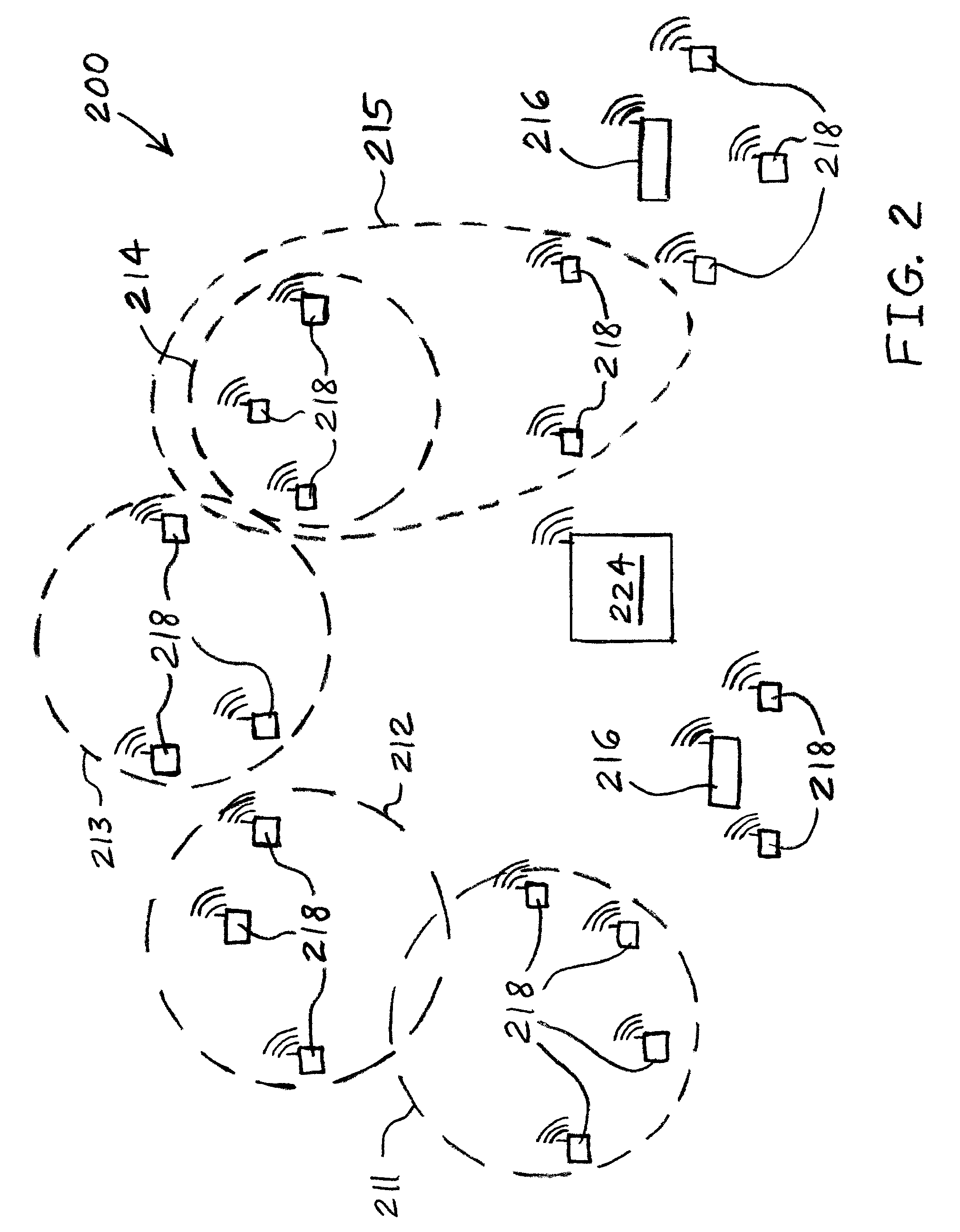
[0036]Referring now to FIG. 2, there is shown an automotive network 200 of the present invention which may circumvent the problems of the prior art by using wireless communication. Network 200 includes sub-networks 211-215 which may each represent a different class of peripherals 218. For example, sub-networks 211-215 may be clusters of pushbutton panels, lights, sensors, small electric motors, and actuator components, respectively. There may be some overlap between sub-networks. For example, the small electric motor sub-network 214 may be a subset of the larger actuator component sub-network 215, as shown in FIG. 2.

[0037]Wireless gateway ECUs 216 may communicate wirelessly, such as via radio frequency communication, ...


PUM


Abstract

An automotive electrical body system includes a plurality of electrical assemblies coupled to at least one automotive body component. Each of the assemblies includes a heating element for heating the at least one component, a motor for actuating the at least one component, or a switch configured to toggle the at least one component on and off. Each of the assemblies also includes a wireless communication module for receiving wireless signals, and, in response to the wireless signals, controlling operation of the heating element or motor. An electrical conductor interconnects each of the electrical assemblies and carries electrical power to each of the electrical assemblies.

Description

BACKGROUND[0001]1. Field of the Invention[0002]The present invention relates to automotive body electrical systems, and, more particularly, to automotive body electrical systems including multiple motors.[0003]2. Description of the Related Art[0004]Typically, automotive body domain applications such as seat control, window lift, mirror adjustment, and light control are distributed over the entire car and are interconnected via field bus communication systems. Current architectures have grown fast over the last decades as more and more convenience functions are introduced to the automotive industry.[0005]The current architectures are hierarchical architectures in which several electronic control units (ECUs) are located near the body domain applications such as the seat ECU under the seat, the door ECU within the door, the ECU for rear light control in the trunk of the car, etc. All these ECUs are interconnected over field bus systems such as the “controller area network” (CAN) field...

Claims


Application Information

Patent Timeline
IPC IPC(8): B60L1/02H02P31/00
CPCB60R16/023
Inventor HOGENMUELLER, THOMASJAIN, VIVEK
Owner ROBERT BOSCH GMBH
Learn More