
Methods of use of particulate materials in conjunction with braze alloys and resulting structures

Inactive Publication Date: 2010-11-18
BAKER HUGHES INC
View PDF18 Cites 9 Cited by
  • Summary
  • Abstract
  • Description
  • Claims
  • Application Information

AI Technical Summary

Benefits of technology

[0010]The present invention comprises the use of abrasive particles in braze a

Problems solved by technology

Common braze joints may be less strong than the parent materials due either to the inherent lower yield strength of the braze alloy or to the low fracture toughness of inter-metallic components.
However, braze welded joints have the disadvantages of loss of strength when subjected to high temperatures.
However, the nozzle assembly is subject to vibration and loading from the flow of drilling fluid therethrough may tend to cause the nozzle assembly to leave the drill bit body if the braze joint used to retain the nozzle assembly in the drill bit is not strong enough to retain the nozzle assembly in the drill bit body.

Method used


Image

  • Methods of use of particulate materials in conjunction with braze alloys and resulting structures
  • Methods of use of particulate materials in conjunction with braze alloys and resulting structures
  • Methods of use of particulate materials in conjunction with braze alloys and resulting structures

Examples


Embodiment Construction

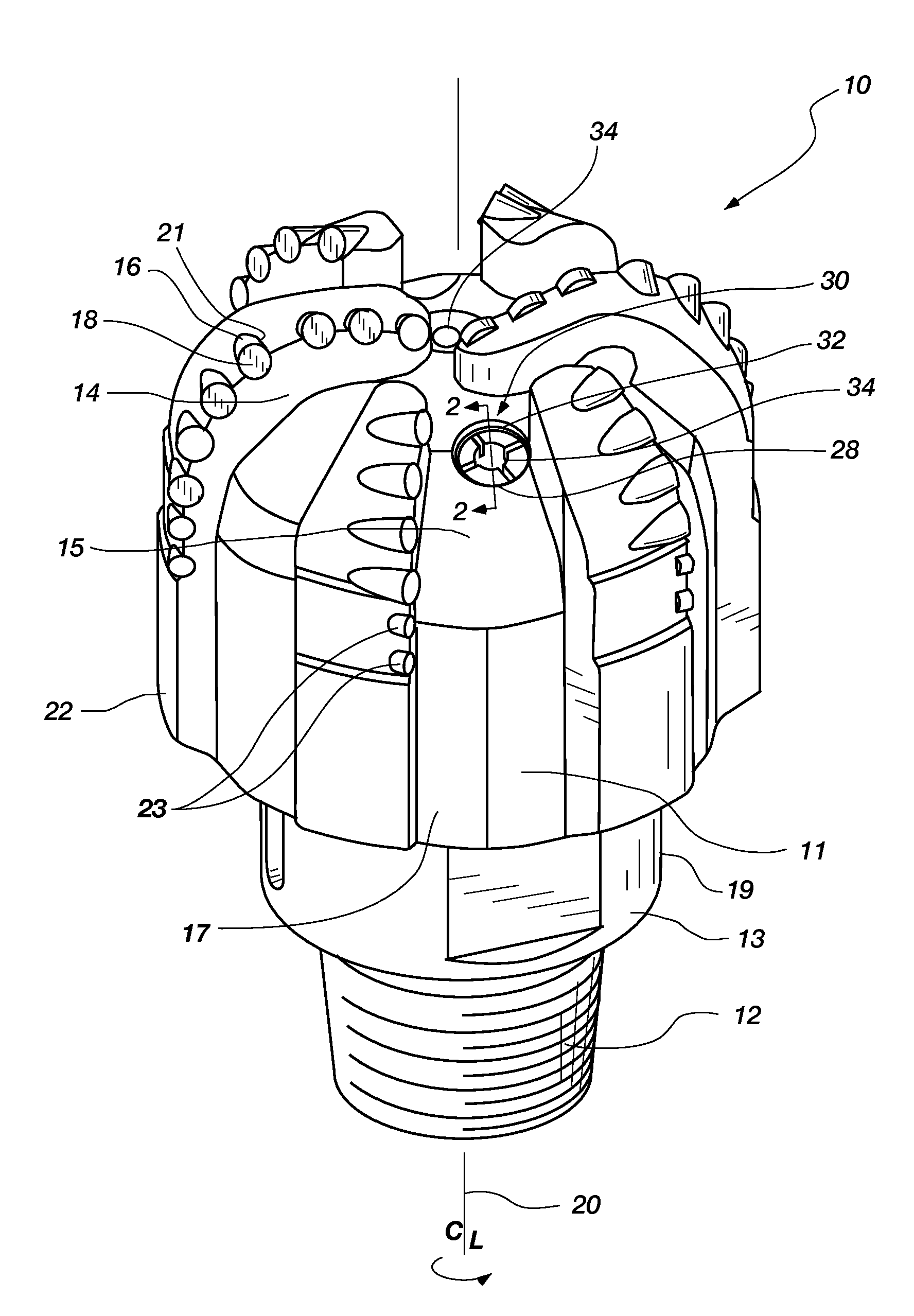
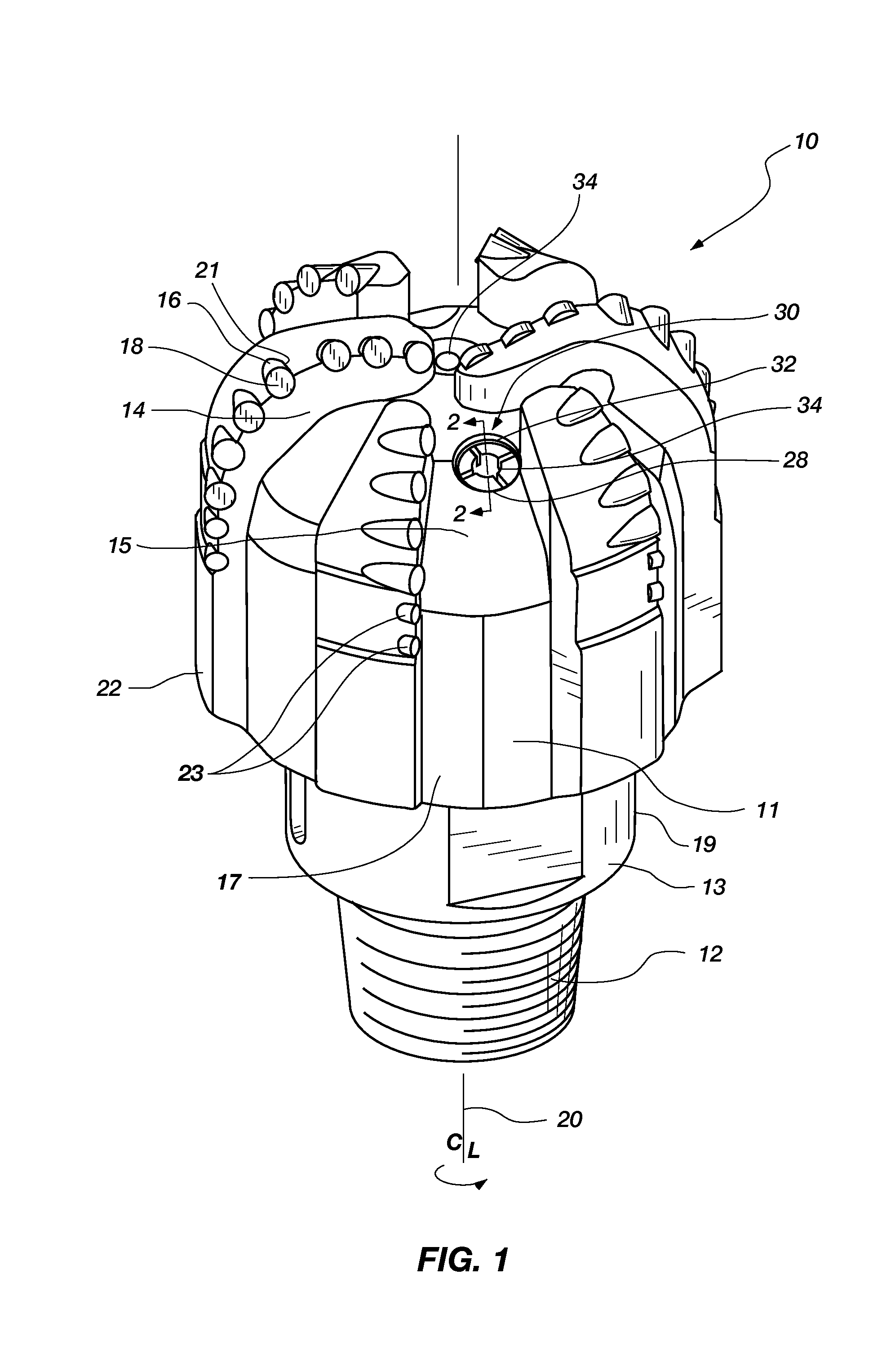
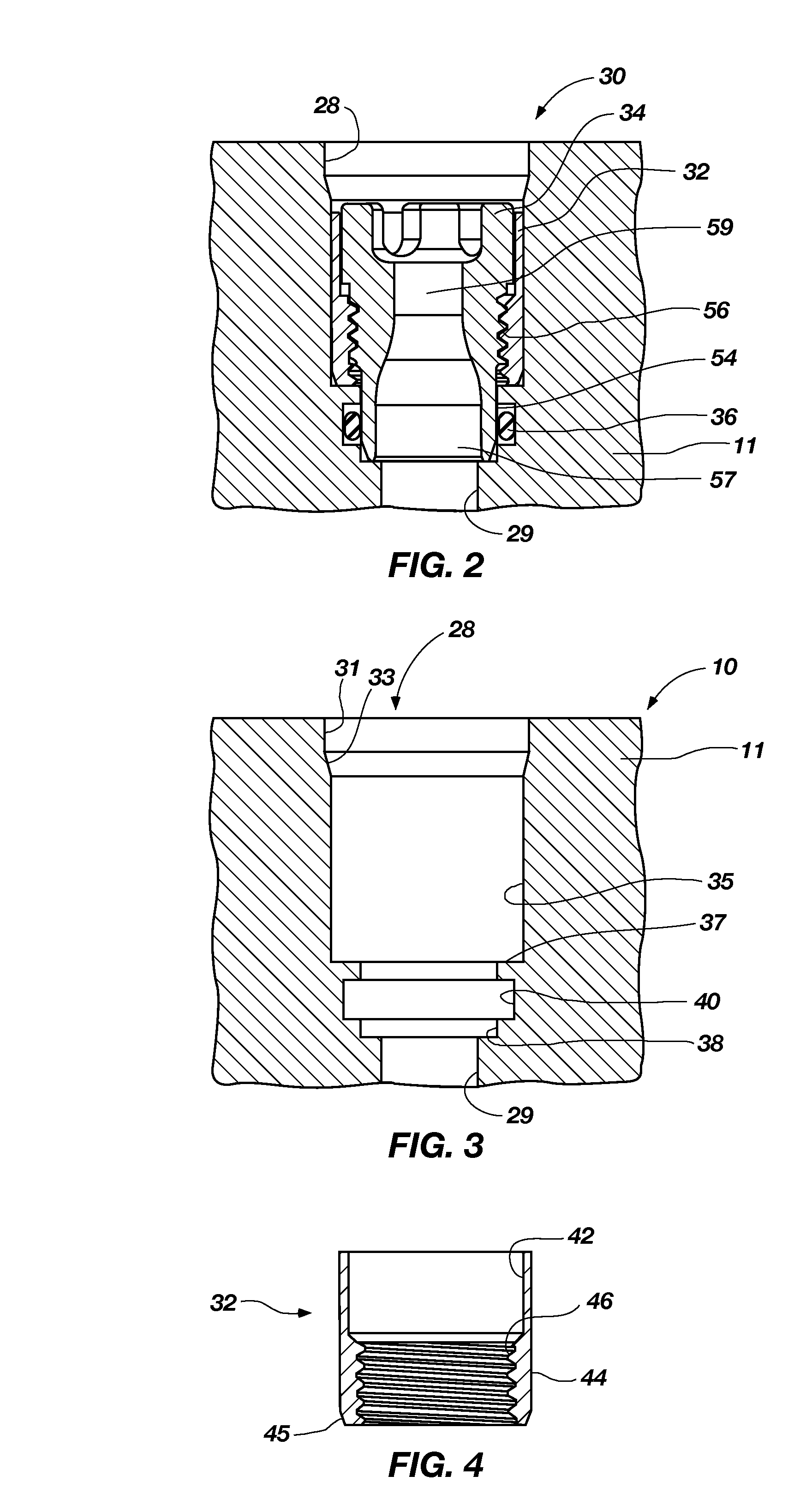
[0016]FIG. 1 shows a drill bit 10 incorporating a plurality of nozzle assemblies 30 according to one or more embodiments of the invention. The drill bit 10 is configured as a fixed cutter rotary full bore drill bit also known in the art as a “drag bit”. The drill bit 10 includes a bit crown or body 11 composed of sintered tungsten carbide coupled to a support 19. The support 19 includes a shank 13 and a crossover component (not shown) coupled to the shank 13 in this embodiment of the invention by using a submerged arc weld process to form a weld joint therebetween. The crossover component (not shown), which is manufactured from a tubular steel material, is coupled to the bit body 11 by pulsed MIG processes to form a weld joint therebetween in order to allow the tungsten carbide material to be securely retained to the shank 13. It is recognized that the support 19, particularly for other materials used to form a bit body, may be made from a unitary material piece or multiple pieces o...


PUM

PropertyMeasurementUnit
Fractionaaaaaaaaaa
Fractionaaaaaaaaaa
Particle sizeaaaaaaaaaa

Abstract

A component brazed to another, constraining component such as sleeve assembly brazed in a bore of a bit body. The braze joint includes particulate material in the gap between the components.

Description

TECHNICAL FIELD[0001]The present invention relates generally to abrasive braze alloys and their methods of use in well tools, such as drill bits, their components and the like.BACKGROUND[0002]Brazing is widely used to join materials by means of a filler material that melts upon heating and coats the surface of materials being joined, creating a bond upon cooling and solidification of the braze material. A suitable filler material wets the surfaces of the materials being joined and allows the materials to be joined without changing the physical properties of the materials. Braze materials generally melt at a low temperature in comparison to the melting temperature of the materials being joined. During a brazing process, heating and cooling of the materials may take place in the open atmosphere or in a controlled atmosphere furnace or vacuum furnace. Braze materials are often based on metals such as Ag, Au, Cu, Ni, Ti, Pd, Pt, Cr, and alloys thereof. Braze base materials may also incl...

Claims


Application Information

Patent Timeline
IPC IPC(8): E21B10/60E21B10/42B23K31/02
CPCB22F7/064B23K1/0008B23K31/025E21B10/60C22C26/00C22C32/0047E21B10/42B23K2201/02B23K2101/02E21B10/61
Inventor SMITH, REDD H.
Owner BAKER HUGHES INC
Learn More