
Light emitting diode devices containing replaceable subassemblies

a technology of light emitting diodes and subassemblies, which is applied in the direction of cathode-ray/electron beam tube circuit elements, lighting and heating apparatus, etc., can solve the problems of heat adding to the cooling load of a system, incandescent light bulbs are very energy-efficient light sources, and the cost per btu of light emitting heat is typically more expensive than the cost per btu of the main heat sour

Inactive Publication Date: 2010-11-04
LED BULB
View PDF16 Cites 37 Cited by
  • Summary
  • Abstract
  • Description
  • Claims
  • Application Information

AI Technical Summary

Benefits of technology

"The present invention is directed to lighting devices that can be easily replaced and repaired. The invention includes a housing that securely holds the lighting components, including solid state light emitters and electronics to activate them. The housing has a specific shape and form factor that matches industry standards. The invention also includes a heat-sinking surface on the housing to improve cooling. The technical effect of the invention is that it allows for the modification and repair of the lighting device, making it more flexible and adaptable to different needs."

Problems solved by technology

It is well known that incandescent light bulbs are very energy inefficient light sources—about ninety percent of the electricity they consume is released as heat rather than light.
This heat adds to the cooling load of a system during cooling season.
In heating season the cost per BTU of heat that the lights give off is typically more expensive than the cost per BTU of the main heat source.
The heat that is given off by the lighting also can cause “over shooting” of the desired temperature which wastes energy and makes the space feel uncomfortable.
Fluorescent light bulbs are more efficient than incandescent light bulbs (by a factor of about four) but are still quite inefficient as compared to solid-state light emitters, such as light emitting diodes (LED's).
In addition, as compared to the normal lifetimes of solid-state light emitters, incandescent light bulbs have relatively short lifetimes, i.e., typically in the range of 750 to 2000 hours.
Fluorescent bulbs have longer lifetimes (e.g., 8,000 to 20,000 hours), but provide less favorable color reproduction.
A practical issue faced by conventional lighting systems is the need to periodically replace the lighting devices (e.g., light bulbs, etc.).
Such issues are particularly pronounced where access is difficult (e.g., vaulted ceilings, bridges, high buildings, traffic tunnels) and / or where change-out costs are extremely high.
In contrast light-producing device lifetimes are typically much shorter, thus creating the need for periodic change-outs.
Although the development of solid state light emitters, e.g., light emitting diodes, has in many ways revolutionized the lighting industry, some of the characteristics of solid state light emitters have presented challenges, some of
which have not yet been fully met.
For example, the emission spectrum of any particular light emitting diode is typically concentrated around a single wavelength (as dictated by the light emitting diode's composition and structure), which is desirable for some applications, but not desirable for others, e.g., for providing lighting, given that such an emission spectrum typically provides a very low CRI.
In such designs, an LED or plurality of LED's are mounted on a circuit board encapsulated within the housing fixture, and a heat sink is typically mounted to the exterior surface of the housing fixture to dissipate heat generated from within the device, the heat being generated by inefficient AC-to DC conversion from with the device.
Typically, designs of this type are configured to be non-repairable when the LED's or other internal components fail, in these cases the devices are simply discarded.
Also, designs of this type make it impossible to “upgrade” the devices to more efficient LED's as they become available.

Method used


Image

  • Light emitting diode devices containing replaceable subassemblies
  • Light emitting diode devices containing replaceable subassemblies
  • Light emitting diode devices containing replaceable subassemblies

Examples


Embodiment Construction

[0026]In general, the present invention is directed to lighting devices, and more particularly to white light LED-based lighting devices configured such that key subassemblies may be replaced, thereby enabling the modification and / or repair of said device.

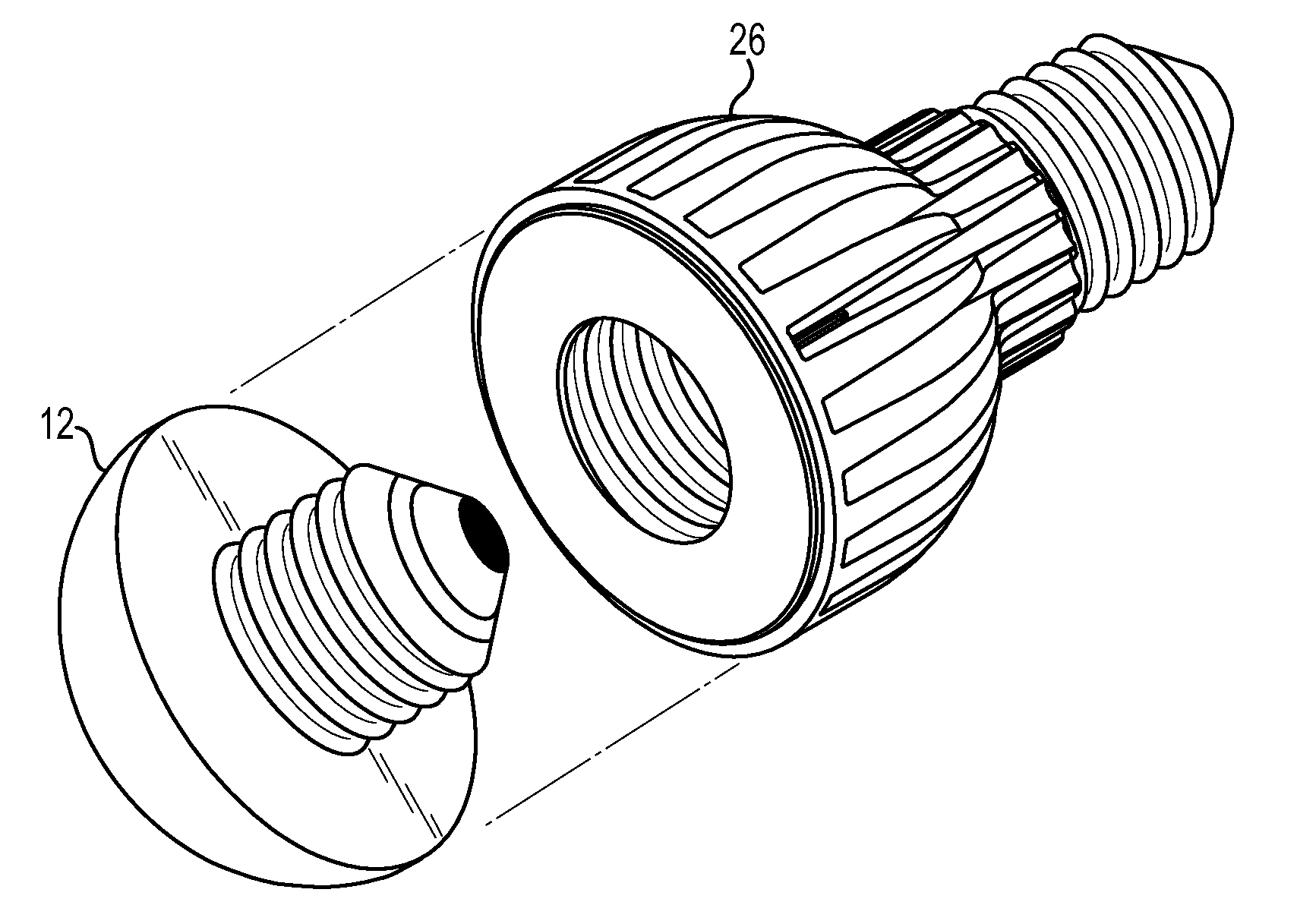
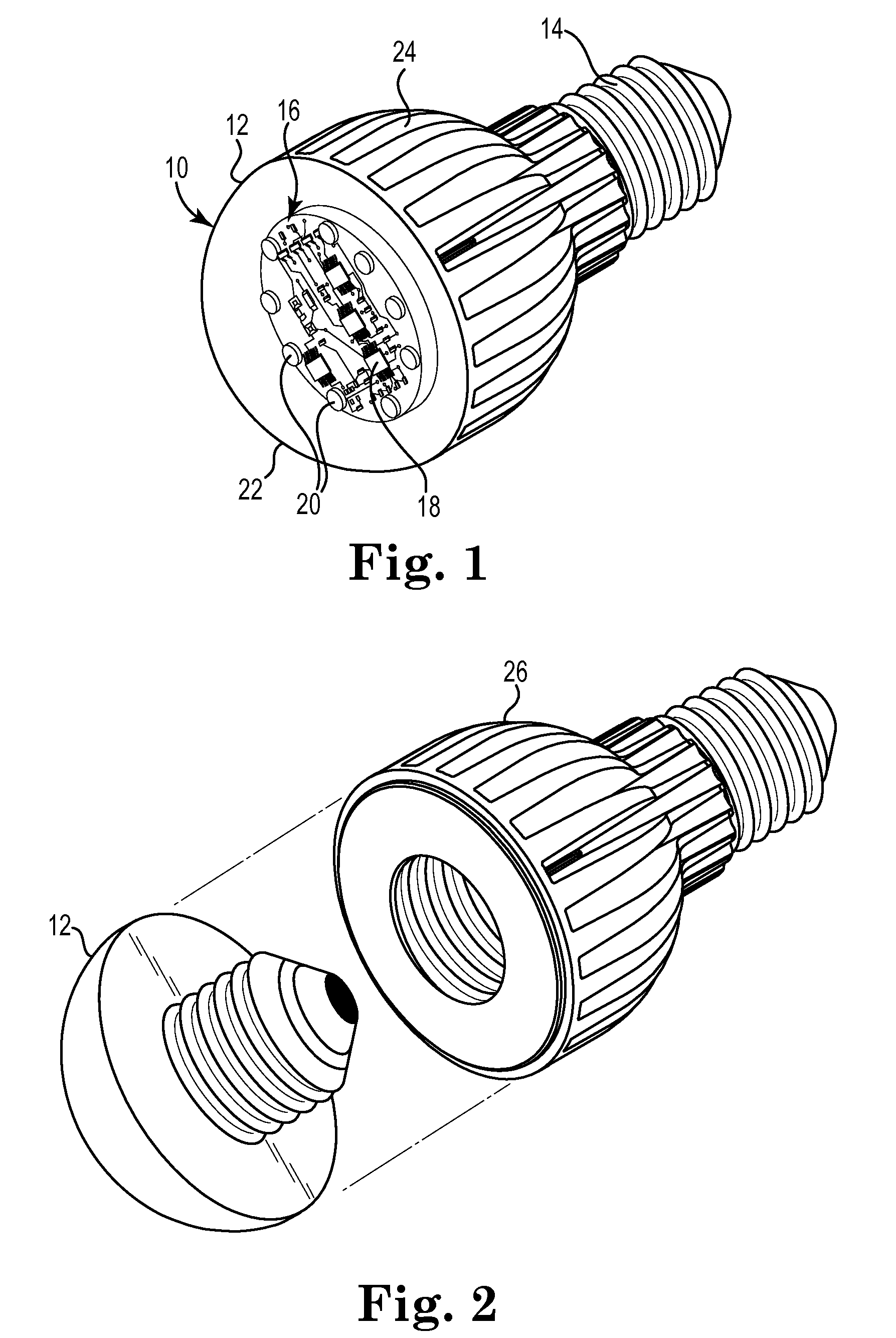
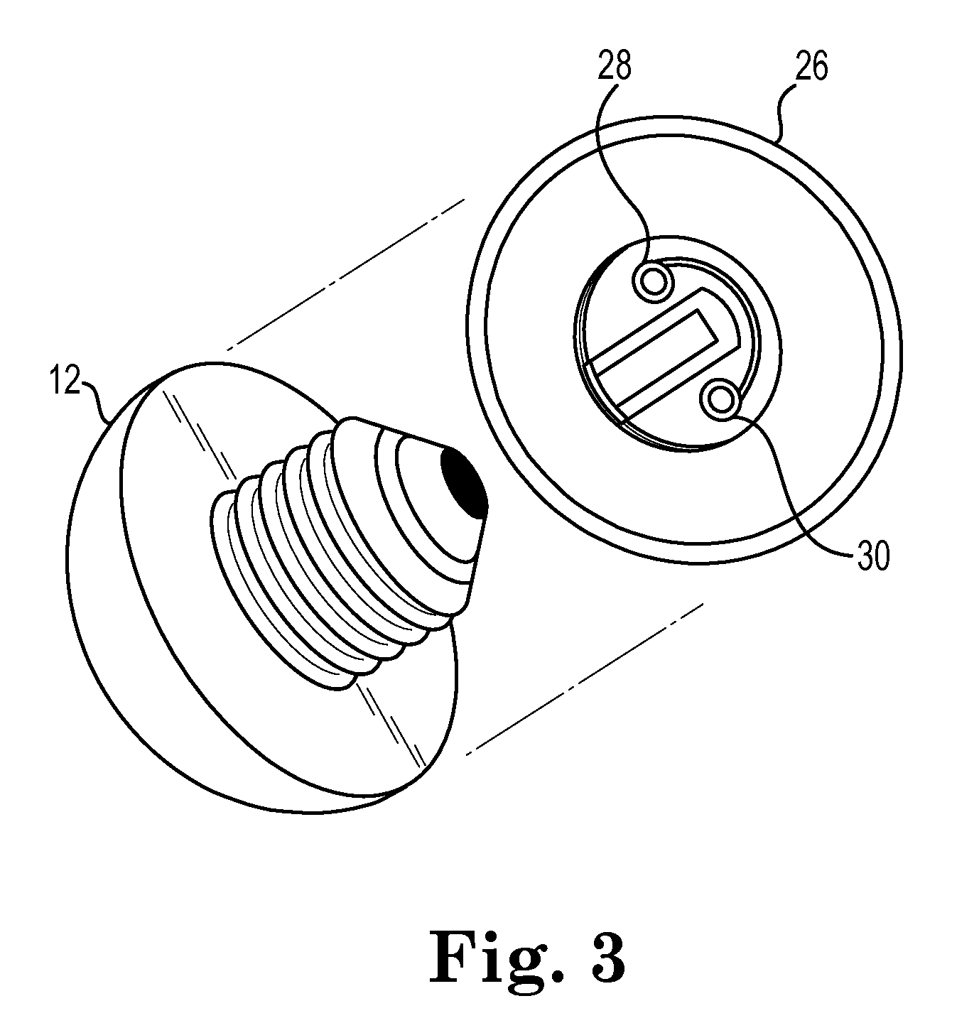
[0027]One embodiment of a white light LED device 10 in accordance with the present invention is depicted schematically in FIG. 1. Incandescent light bulb devices with the shape and form factor depicted in FIG. 1 have generally been categorized by the American National Standards Institute (ANSI) as having part numbers R-20, R-30, R-38 and / or R-40, the difference being their height and diameter, increasing with higher numerical designation. Alternative incandescent devices have been designed with a similar, but not identical, shape and form factor incorporating a slight bulge in their base section and have been designated by ANSI with a “BR” prefix to highlight this feature. For example, the BR-20 incandescent light bulb has a simila...


PUM


Abstract

The present invention is directed generally to lighting devices, and more particularly to white light LED-based lighting devices configured such that key subassemblies may be replaced, thereby enabling the modification, upgrade and / or repair of said device.

Description

CROSS-REFERENCE TO RELATED APPLICATIONS[0001]The present application claim the benefit of and priority to U.S. Provisional Application Ser. No. 61 / 215,106 Filed of May 1, 2009 the entire content of which being incorporated herein by reference.FIELD OF THE INVENTION[0002]The present invention is directed generally to lighting devices, and more particularly to white light LED-based lighting devices configured such that key subassemblies may be replaced, thereby enabling the modification and / or repair of said device.BACKGROUND[0003]Energy conservation, in all its varied forms, has become a national priority of the United States as well as the rest of the world, from both the practical point of view of limited natural resources and recently as a security issue to reduce our dependence on foreign oil. A large proportion (some estimates are as high as one third) of the electricity used in residential homes in the United States each year goes to lighting. The percentage is much higher for ...

Claims


Application Information

Patent Timeline
Patent Type & Authority Applications(United States)
IPC IPC(8): H01K1/62H01J9/50
CPCF21Y2101/02F21V19/0055F21V19/045F21V29/773F21V23/06F21K9/13F21Y2113/005F21V23/005F21V19/04F21K9/20F21K9/23F21K9/238F21Y2113/13F21Y2115/10
Inventor BROITZMAN, TROY RICHARD
Owner LED BULB
Learn More