
Static mixing device, and production method

Inactive Publication Date: 2010-10-21
GRUBER & GROUP
View PDF2 Cites 3 Cited by
  • Summary
  • Abstract
  • Description
  • Claims
  • Application Information

AI Technical Summary

Benefits of technology

[0004]The invention is thus based on the object of providing a mixing device which ensures good temperature compensation over the flow cross section of extruded plastic strands, especially on the basis of polyvinyl chloride, without needing to fear any local thermal overstressing of the plastic strand.
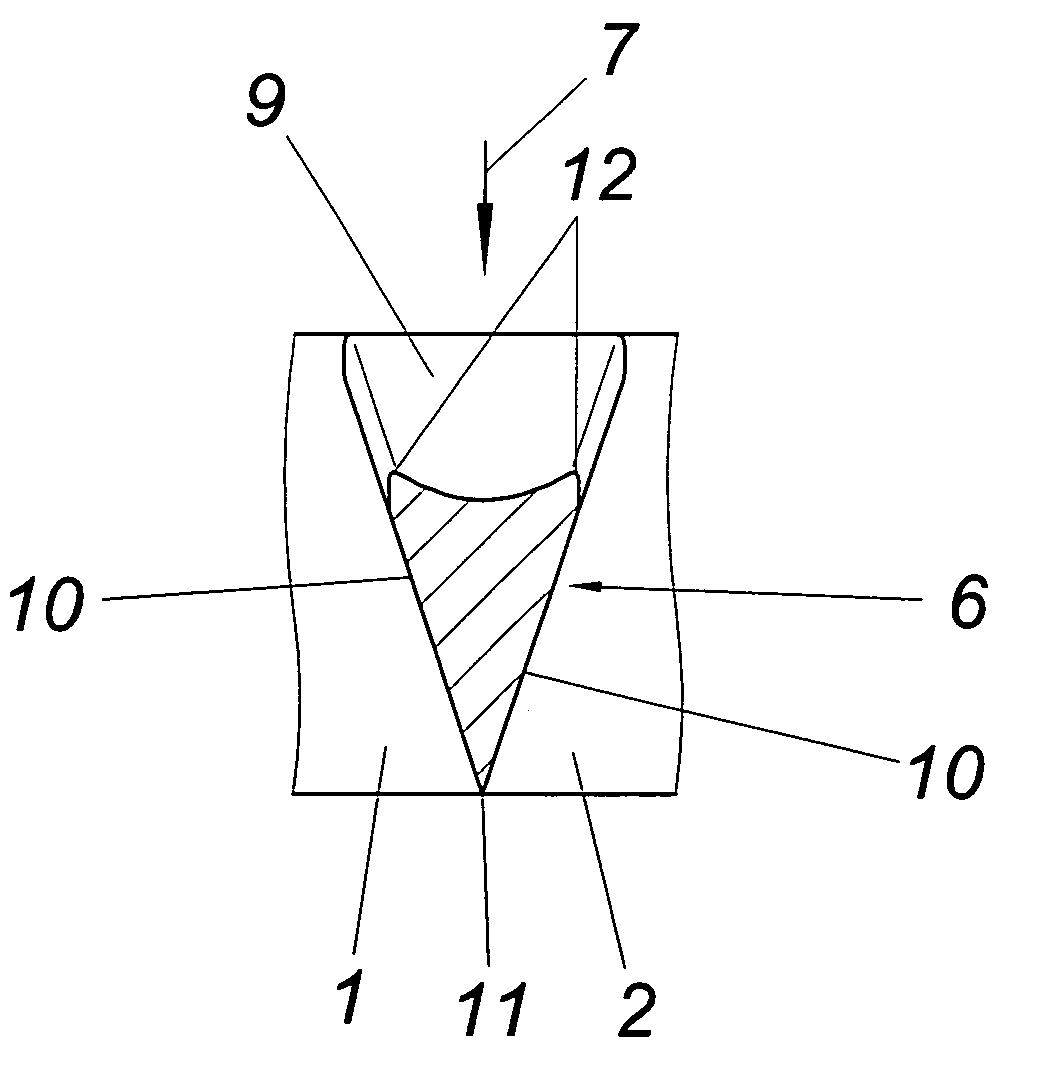
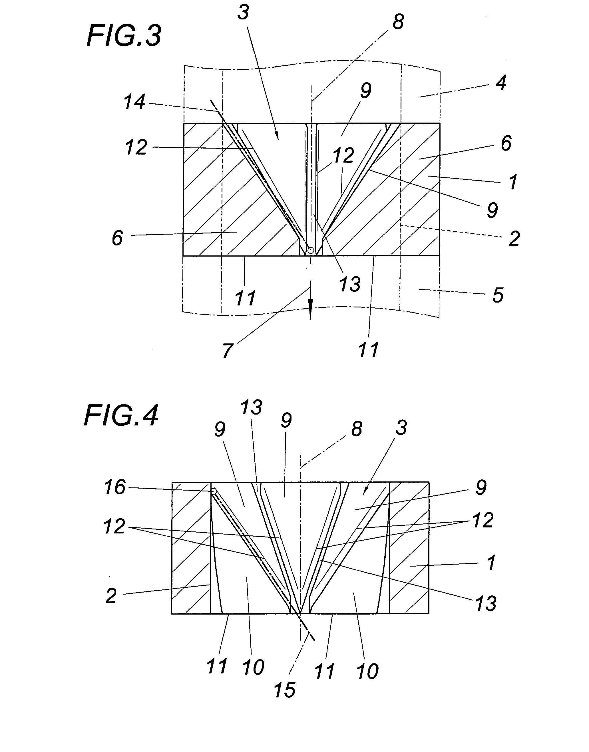
[0006]As a result of the deflecting surfaces preferably rising in the direction of flow, the molten plastic strand is deflected towards the channel axis, which leads to a displacement radially to the outside for the partial flows extending in the region of the pass-through slits between the flow bodies, so that a respective mixture over the flow cross section and thus a substantial temperature compensation is obtained. As a result of the rounded portion of at least the flow edges between the guide surfaces and the deflecting surface of the flow bodies, a laminar flow of the molten plastic strand can be maintained since the guide surfaces prevent dead spaces of the flow, which guide surfaces are adjacent to the deflecting surface along the pass-through slits and intersect with a substantially radially extending edge in the region of the individual flow bodies, and delimit a flow path continually expending in the direction of flow together with the opposite guide surfaces of the respectively adjacent flow bodies, in which path other partial flows are subjected to a radial displacement to the outside in the partial flows guided to the inside along the deflecting surface. Since the flow bodies fill out the flow cross section of the flow channel in a project in the direction of the channel axis with the exception of pass-through slits, substantially the entire flow cross section of the molten plastic strand is captured by the mixing elements, representing a far from inconsiderable precondition for a radial displacement of partial flows for the purpose of a substantial temperature compensation over the cross section of the plastic strand. Although the flow from the base of the deflecting surface of the flow bodies against the mixing elements is preferred, a flow in the opposite direction is also possible because comparable mixing effects are obtained in the through-flow of the mixing device in the opposite direction as a result of the laminar flow conditions.
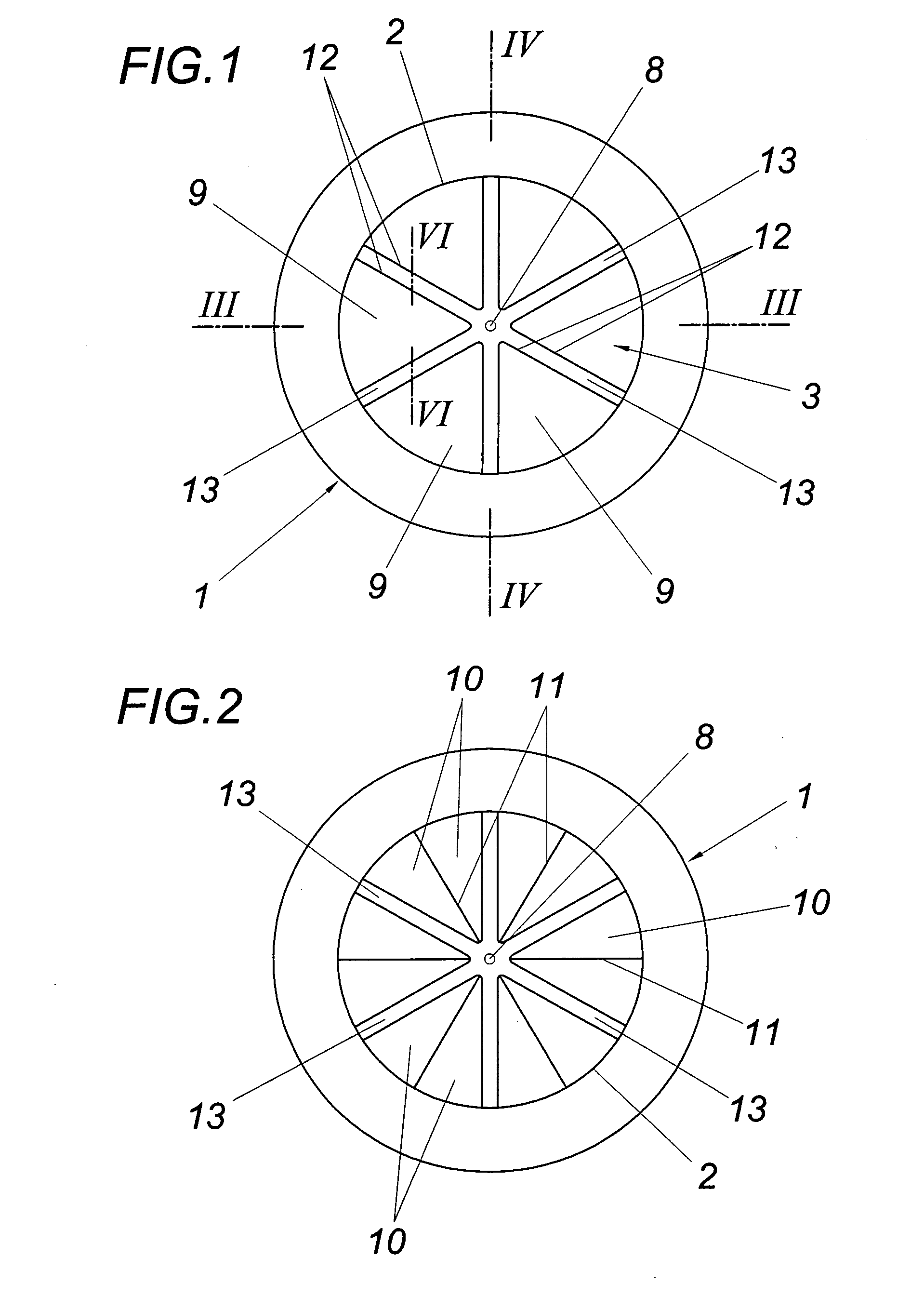
[0007]Although the mixing device is substantially independent of the flow cross section of the flow channel, especially advantageous mixing conditions are obtained when the flow channel is arranged in a circular-cylindrical way, with the deflecting surfaces of the flow body being disposed on a conical surface with an axis of the cone coinciding with the channel axis, so that a transition from a circular flow cross section to the flow channel of the mixing device is obtained, which offers little obstruction to the flow of the molten plastic strand, thus having an advantageous effect on the pressure requirements for the mixing device. Especially simple constructional conditions are obtained in this connection when the flow bodies are arranged in a rotational-symmetrical manner about the channel axis, leading to symmetrical mixing conditions. If non-symmetrical temperature distributions are expected over the cross section of the plastic strand, it is possible to provide a non-symmetrical distribution of the flow bodies that takes such non-symmetrical temperature distribution into account or a different arrangement of the pass-through slits between the individual flow bodies.

Problems solved by technology

These deflecting surfaces in the form of guide surfaces additionally lead to a turbulence supporting the mixing.
However, this leads to the likelihood of local damage to the plastic as a result of longer dwell times for thermally sensitive plastic materials, e.g. on the basis of polyvinyl chloride.
Due to the desired turbulence of the fluids to be mixed, such static mixing devices are not suitable for mixing thermally sensitive plastic melts such as those on the basis of polyvinyl chloride.

Method used


Image

  • Static mixing device, and production method
  • Static mixing device, and production method
  • Static mixing device, and production method

Examples


Embodiment Construction

[0016]The illustrated static mixing device has a circular-cylindrical jacket 1, the inside surface 2 of which forms a flow channel 3 for a molten plastic strand, especially on the basis of polyvinyl chloride, which is supplied and discharged via circular-cylindrical conduits 4, 5, as is indicated in FIG. 3 with the dot-dash line. Mixing elements protrude into the flow channel 3 from the inside surface 2 of jacket 1. These mixing elements have the shape of flow bodies 6, of which one is shown in closer detail in FIGS. 5 and 6. This illustration shows that the flow bodies 6, according to the direction of flow 7 chosen in the embodiment which is not mandatory, comprise a deflecting surface 9 which is inclined from a base extending transversally to the direction of flow 7 towards the axis 8 of the flow channel 3 and two lateral guide surfaces 10 which converge into one edge 11 protruding radially from the inside surface 2. The flow edges 12 obtained between the guide surfaces 10 and the...


PUM


Abstract

A static mixing device is described, comprising a flow channel and mixing elements which are distributed over the cross section of the flow channel in the form of flow bodies arranged on a wall extending in the direction of flow and which are each delimited by one tapering deflecting surface which is inclined in relation to the wall and originates from a base extending transversally to the direction of flow and by two guide surfaces which protrude from the wall and which converge in an edge extending transversally to the channel axis on the side of the flow bodies which is opposite of the base. In order to provide advantageous mixing conditions for thermally sensitive plastic materials it is proposed that the flow bodies (6) arranged on the channel wall fill out the flow cross section in a projection in the direction of the channel axis (8), with the exception of the pass-through slits (13) between the flow edges (12) obtained between the guide surfaces (10) and the deflecting surface (9), and at least the flow edges (12) between the guide surfaces (10) and the deflecting surface (9) of the flow bodies (6) are rounded off.

Description

1. FIELD OF THE INVENTION[0001]The invention relates to a static mixing device, comprising a flow channel and mixing elements which are distributed over the cross section of the flow channel in the form of flow bodies arranged on a wall extending in the direction of flow and which are each delimited by one tapering deflecting surface which is inclined in relation to the wall and originates from a base extending transversally to the direction of flow and by two guide surfaces which protrude from the wall and which converge in an edge extending transversally to the channel axis on the side of the flow bodies which is opposite of the base.2. DESCRIPTION OF THE PRIOR ART[0002]A molten plastic strand with a temperature distribution which is uneven over the cross section is obtained especially in connection with double-screw extruders during the extrusion of plastic, leading among other things to different wall thicknesses of plastic profiles which are formed with the help of shaping nozz...

Claims


Application Information

Patent Timeline
IPC IPC(8): B01F5/06B23H9/00
CPCB01F5/061B29B7/325B23H9/00B23H7/02B01F25/431B01F25/431971
Inventor KRUMBOECK, ERWIN
Owner GRUBER & GROUP
Learn More