
Electrical devices with light source

a technology of electronic devices and light sources, applied in the direction of electrical equipment, printed circuit aspects, lighting and heating apparatus, etc., can solve the problems of loss of data, data loss, and unsuitability of usb flash drives for reliably storing important data, etc., to achieve high reliability, easy to handle and use, and shock resistance and robustness

Inactive Publication Date: 2010-10-21
MOSER BAER INDIA
View PDF3 Cites 2 Cited by
  • Summary
  • Abstract
  • Description
  • Claims
  • Application Information

AI Technical Summary

Benefits of technology

[0009]Another embodiment relates to a storage device that is highly reliable, shock resistant, water resistant and robust, compared to conventional storage devices.
[0010]Yet another embodiment relates to a storage device that is miniature in size, and is easy to handle and use, compared to conventional storage devices.
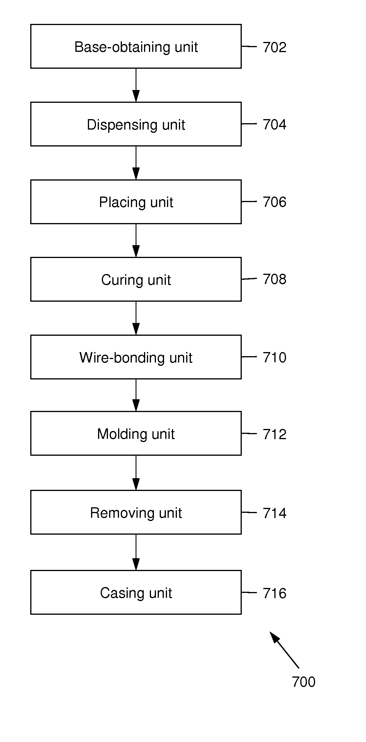
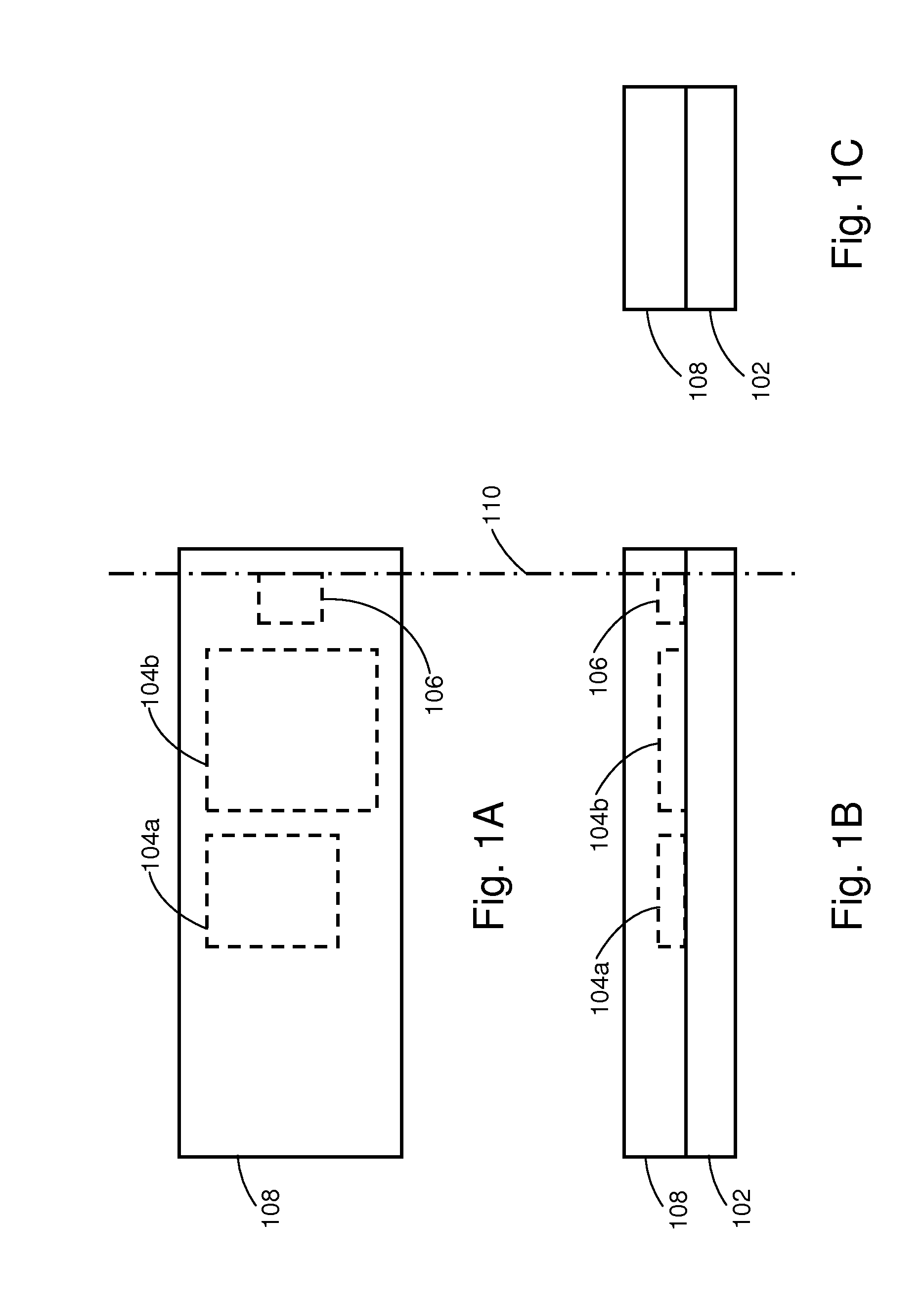
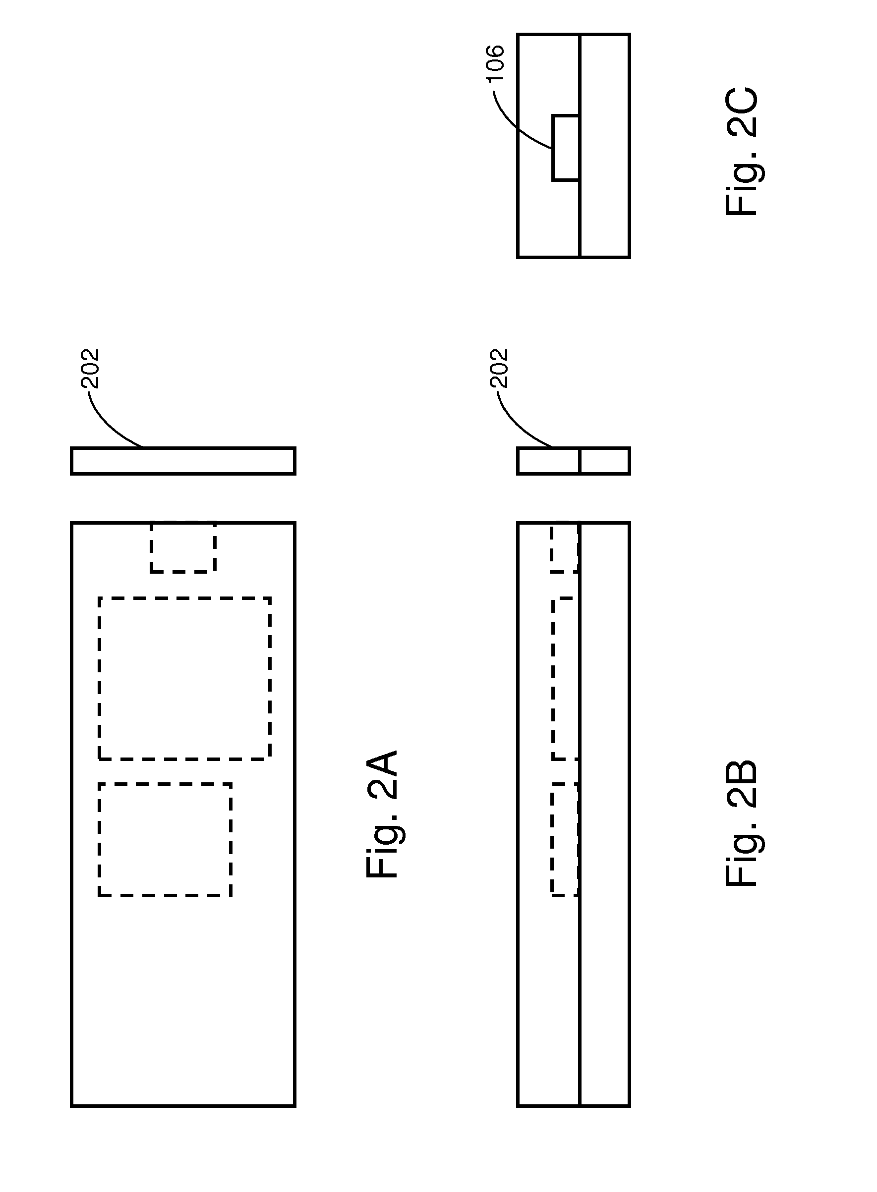
[0012]A molding material is molded over the electrical components and the light source, wherein the light source is partially visible. In accordance with an embodiment herein, the molding material is molded over a surface of the base substrate on which the electrical components and the light source are placed. The molding material encapsulates the electrical components and the light source hermetically. This makes the electronic device highly reliable, shock resistant, water resistant and robust.
[0017]In one embodiment herein, a COB type storage device is manufactured by a COB process. As the COB process requires less space, a base substrate of a small size may be used. The COB type storage device so manufactured is miniature in size, and therefore, is easy to handle and use.

Problems solved by technology

However, conventional encapsulation techniques often encapsulate various components of the USB flash drive in a non-hermetic seal.
This may lead to loss of data when moisture or water comes in contact with the USB flash drive.
The data may also be lost due to rough handling of the USB flash drive.
This makes such USB flash drives unsuitable for storing important data reliably.
Additionally, conventional USB flash drives are larger in size, which adds to inconvenience of end users.
Whenever an attempt to miniaturize a USB flash drive is made, light indicators are sacrificed due to inherent complexity of the process of manufacturing miniaturized USB flash drives, as well as to reduce size.
Removal of the light indicator causes inconvenience to the end users, who remain unaware of the state of the USB flash drive.

Method used


Image

  • Electrical devices with light source
  • Electrical devices with light source
  • Electrical devices with light source

Examples


Embodiment Construction

[0031]As used in the specification and claims, the singular forms “a”, “an” and “the” include plural references unless the context clearly dictates otherwise. For example, the term “a light source” may include a plurality of light sources unless the context clearly dictates otherwise.

[0032]Embodiments herein provide a method of manufacturing an electronic device, and electronic devices manufactured thereof. In the description of the embodiments herein, numerous specific details are provided, such as examples of components and / or mechanisms, to provide a thorough understanding of embodiments herein. One skilled in the relevant art will recognize, however, that an embodiment herein can be practiced without one or more of the specific details, or with other apparatus, systems, assemblies, methods, components, materials, parts, and / or the like. In other instances, well-known structures, materials, or operations are not specifically shown or described in detail to avoid obscuring aspects...


PUM

PropertyMeasurementUnit
heightaaaaaaaaaa
heightaaaaaaaaaa
widthaaaaaaaaaa

Abstract

An electronic device with a light source is provided. The electronic device includes a base substrate, one or more electrical components placed on the base substrate, and a light source placed on the base substrate. The electrical components and the light source are electrically connected in a pre-defined manner. A molding material is molded over the electrical components and the light source, wherein the light source is partially visible.

Description

CROSS-REFERENCE TO RELATED APPLICATION[0001]This application claims the benefit of priority under 35 U.S.C 119 to co-pending India Patent Application No. 998 / CHE / 2009 filed on Apr. 29, 2009, India Patent Application No. 936 / CHE / 2009 filed on Apr. 22, 2009, and India Patent Application No. 899 / CHE / 2009 filed on Apr. 20, 2009. The entire disclosure of the prior applications is incorporated herein by reference.BACKGROUND OF THE INVENTION[0002]1. Field of the Invention[0003]The embodiments herein relate, in general, to electronic devices. More particularly, the embodiments relate to a method of manufacturing an electronic device with a light source.[0004]2. Description of the Prior Art[0005]Universal Serial Bus (USB) flash drives are more common these days than any other portable storage devices. A USB flash drive is typically manufactured using Surface Mount Technology (SMT) in which a flash Integrated Circuit (IC) and other supporting electrical components are mounted on a Printed Cir...

Claims


Application Information

Patent Timeline
Patent Type & Authority Applications(United States)
IPC IPC(8): F21V33/00B29C67/00B29C35/08
CPCH05K3/284H05K5/0278H05K2203/1316H05K2201/10159H05K2201/10106
Inventor SINGH, JITENDER PRATAPMALHI, VIJAY
Owner MOSER BAER INDIA
Learn More