
Congestion control in a communication network based on the csma/ca protocol

a communication network and protocol technology, applied in data switching networks, frequency-division multiplexes, instruments, etc., can solve the problems of reducing the qos of services, affecting the quality of services, and reducing so as to improve the quality of services, and ensure the effect of receiving

Active Publication Date: 2010-10-14
KONINKLIJKE PHILIPS ELECTRONICS NV
View PDF6 Cites 6 Cited by
  • Summary
  • Abstract
  • Description
  • Claims
  • Application Information

AI Technical Summary

Benefits of technology

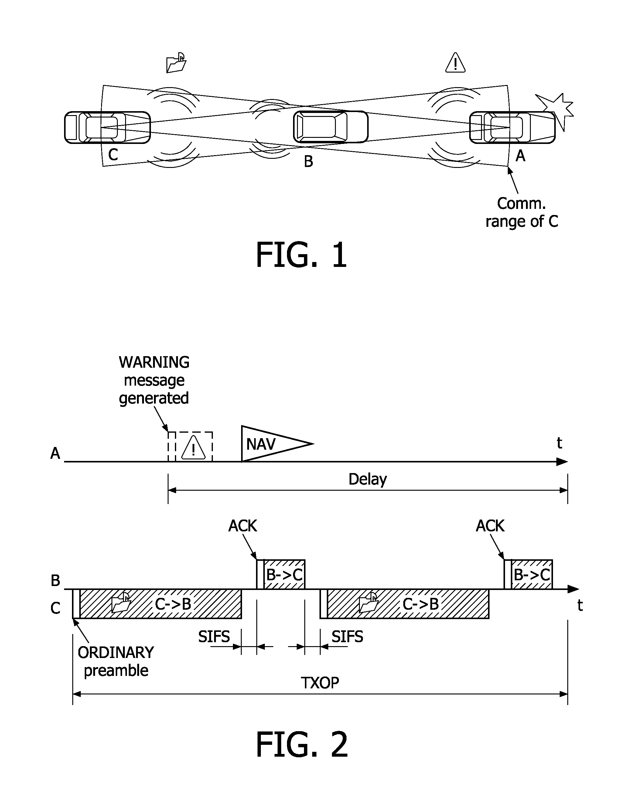
[0011]This provides the advantage that the congestion control is improved and this is especially advantageous in networks that offer services of two different types which are assigned different priorities. Examples of such services are for instance safety and non-safety applications. In these cases, the safety services are advantageously given higher priority and even if the network is congested, the safety messages can be transmitted and reliably received by terminals operating in the network.

Problems solved by technology

The results of congestion are the degradation of QoS for the services, i.e. lower throughput, higher end-to-end packet delay, or even discard of packets in some severe cases.
However, in systems where the channel resource is shared by services with a priority of the first order, such as safety applications, and services with a priority of the second order, such as non-safety applications, e.g. IEEE 802.11p, the QoS of the safety applications may be compromised due to the channel congestion caused by the non-safety applications.
In these systems, where the channel resource is shared by safety and non-safety services, non-safety applications may exhaust the channel resource, even if a higher priority has been assigned to the safety applications.

Method used


Image

  • Congestion control in a communication network based on the csma/ca protocol
  • Congestion control in a communication network based on the csma/ca protocol
  • Congestion control in a communication network based on the csma/ca protocol

Examples


Embodiment Construction

[0025]In the following description some non-limiting exemplary embodiments of the invention will be described in more detail in the context of DCF in a CSMA / CA system. However, it is to be understood that the invention is not restricted to this environment, but the teachings of the invention are equally applicable in communication systems employing other multiple access schemes such as frequency division multiple access (FDMA). More specifically the CSMA / CA system, where some embodiments of the invention are described in more detail is an IVC system, where the physical and MAC layers are implemented in accordance with the IEEE 802.11p standards.

[0026]IEEE 802.11p has now become a worldwide WLAN standard for IVC systems. From the point of view of physical layer the frequency channel is divided into several channels for control and safety services or non-safety services. The channel for control and safety use can also be referred to as a control channel (CCH). The DCF, as the basic ac...


PUM


Abstract

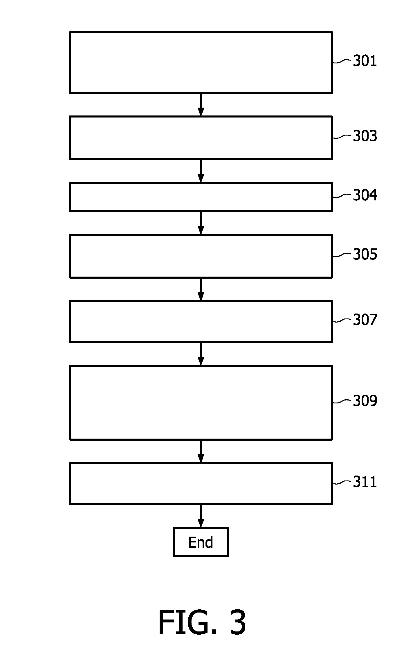
The present invention relates to a congestion control method for a communication system supporting layered radio channel structure for communication between at least a first communication device and a second communication device, the layered structure comprising at least a physical layer and a medium access layer. The communication system is arranged to offer a first type of service with a first priority order and a second type of service with a second priority order, in the communication system messages comprising a preamble and a payload can be transmitted between devices, each message being separated by at least a period corresponding to a minimum allowable period between two messages. In the method the first communication device first (a) generates (301) a physical layer message pertaining to the first type of service; (b) senses (303) the radio channel idle for at least a period corresponding to the minimum allowable period between two messages; and (c) transmits (305) the physical layer message comprising a special preamble indicative of the type of service the message pertains, wherein the content of the preamble is arranged to be detected by the second communication device within a communication range irrespective of the decoding state of the payload of the transmitted message.

Description

TECHNICAL FIELD[0001]The present invention relates to a congestion control method for a communication system. The invention also relates to a corresponding computer program product and communication device.BACKGROUND OF THE INVENTION[0002]In wireless communication networks congestion control is an issue that needs to be addressed in order to have a network that operates smoothly thereby providing good quality of service (QoS) to its users. By “congestion” in communication networks is usually understood a situation, where the network is unable to deliver the offered load due to the insufficient capacity or overloaded traffic. The results of congestion are the degradation of QoS for the services, i.e. lower throughput, higher end-to-end packet delay, or even discard of packets in some severe cases.[0003]Communication networks are known, which can provide two different types of services in terms of safety. First class of services includes only services related to safety or security, wh...

Claims


Application Information

Patent Timeline
IPC IPC(8): H04L12/26
CPCH04L12/4135H04L47/10H04W74/0875H04L47/2408H04L47/14H04W28/02H04W28/24H04W74/08H04W8/04
Inventor REUMERMAN, HANS-JUERGENHIERTZ, GUIDO ROLANDZANG, YUNPENGMAX, GUSTAF SEBASTIANSTIBOR, LOTHARWALKE, BERNHARD
Owner KONINKLIJKE PHILIPS ELECTRONICS NV
Learn More