Solid step drill

a drill bit and step technology, applied in the direction of twist drills, manufacturing tools, wood boring tools, etc., can solve the problems of non-solid drills, high costs, and discarded or, if possible, regrounding

Active Publication Date: 2010-10-07
SANDVIK INTELLECTUAL PROPERTY AB
View PDF22 Cites 31 Cited by
  • Summary
  • Abstract
  • Description
  • Claims
  • Application Information

AI Technical Summary

Benefits of technology

[0011]The invention is based on the understanding that the difficulties with the chip formation and the chip evacuation in solid step drills can be overcome by forming in the vicinity of at least one of the secondary cutting edges (and suitably both) a recess, in which the chip immediately after the commenced removal can dive in and during its passage be formed along the limiting surface of the recess and / or broken off before it enters the proper chip flute. This means that the chip formation is not exposed to unpredictable conditions of the type that are at hand when the (concave or plane) limiting surface of the chip flute extends all the way up to the cutting edge line of the cutting edge in question.

Problems solved by technology

A drawback with solid drills is, however, that they have to be either discarded or, if possible, reground when the cutting edges have been worn out.
This may at times cause expenses that may be high.
A disadvantage of all types of non-solid drills is, however, that the drill body and the cutting edge-carrying wear parts are not integrated with each other, but rather of mutually different nature, above all in respect of the properties of the different materials (e.g., steel / cemented carbide), besides which the wear parts have to be connected or interconnected with the basic body via interfaces in which sources of error may arise.
In other words, non-solid drills are less reliable when high precision is desired.
However, other, more ductile materials, such as low-carbon steel, aluminium, copper, titanium and acid-proof steel, generate most often long chips which are difficult to handle, which may cause the most detrimental problems such as chip jamming, impaired hole quality, entanglement in the driving machine, and even risks of accidents.
In step drills, these problems may become accentuated as a consequence of the fact that at least two types or sets of long chips are to be evacuated via mutual chip flutes, viz. not only a first set generated by the primary cutting edges in the tip of the drill, but also at least one second set generated by the secondary cutting edges in the step or steps of the drill.
Because all chips have to be evacuated via common chip flutes, the risk of entanglement and chip jamming becomes extra great.
In the last-mentioned case, the chip is directed more radially and therefore gets an increased tendency to coil into tangles that may cause severe chip jamming.
A disadvantage of non-solid drills in general and, in particular, of step drills is, however, that various sources of error may occur in connection with the mounting or fastening of the separate cutting inserts, more precisely in respect of the position precision of the cutting inserts and cutting edges in relation to the rest of the drill body.
For this reason, non-solid step drills are poorly suitable for such hole making where the requirements of the position precision of the holes are particularly great.

Method used


Image

  • Solid step drill
  • Solid step drill
  • Solid step drill

Examples


Embodiment Construction

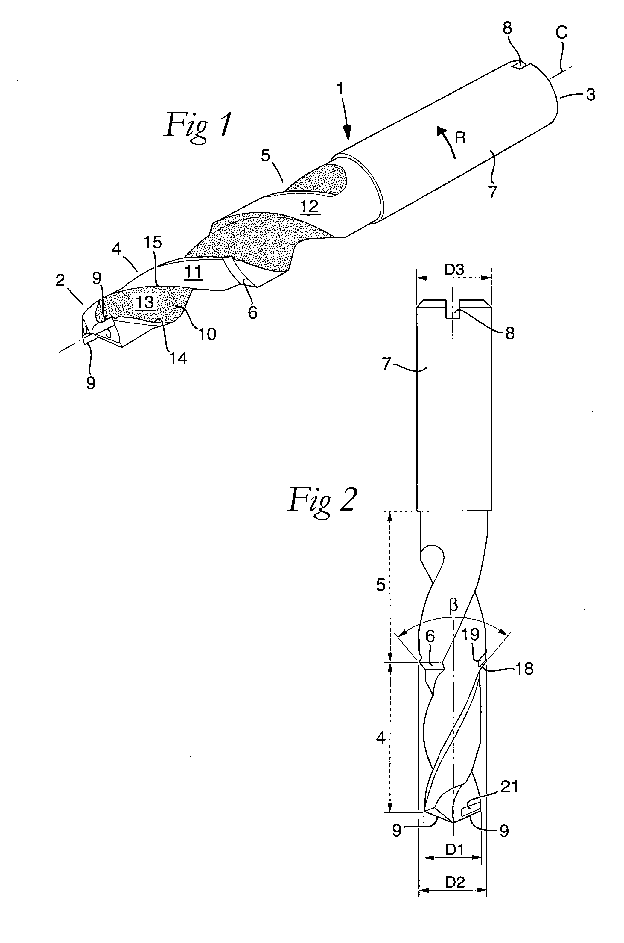
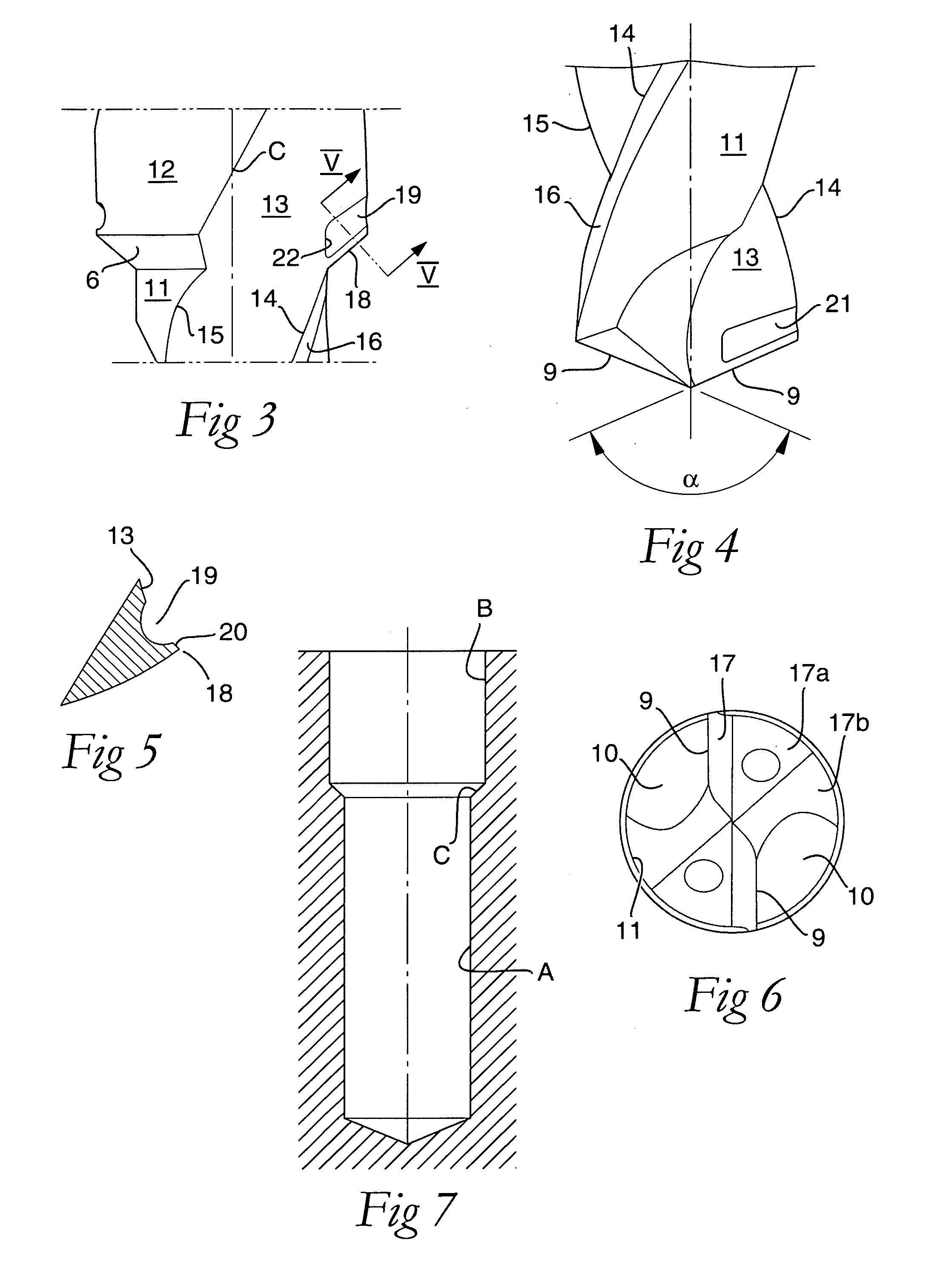
[0022]In the drawings, the embodiment is exemplified in the form of a solid step drill made as a twist drill, i.e., the chip flutes of the drill are in this case helicoidal (contrary to the straight chip flutes found in so-called tap borers). The drill is in the form of a long narrow body 1, which comprises a front tip 2 and a rear end 3 between which a center axis C extends around which the drill is rotatable in a predetermined direction R. Two essentially cylindrical sections in the body are concentric with the center axis C, viz. a first, front section 4 that extends rearward from the tip 2, and a second section 5 being behind, which is spaced-apart from the first section via a so-called step 6. As is seen in FIG. 2, the front section 4 has a diameter D1 that is smaller than the diameter D2 of the second section 5. In this case, also a rear fastening part 7, the diameter D3 of which is greater than D2, is included in the drill. For the transfer of torque to the drill, the fasteni...


PUM

PropertyMeasurementUnit
diameteraaaaaaaaaa
step angleaaaaaaaaaa

Abstract

A solid step drill, including a front tip and a rear end between which a center axis extends and around which the drill is rotatable in a predetermined direction. At least two cylindrical sections are concentric with the center axis, a first section extending rearward from the front tip and having a first diameter, and a second section extending behind the first section and having a second diameter that is greater than the first diameter, the first section transforming into the second section via a step. The tip includes two primary cutting edges, which individually co-operate with a respective chip flute that is delimited by a concave surface and countersunk in the first section and in the second section, the respective chip flute intersecting the step while forming a secondary cutting edge. Adjacent to the secondary cutting edge, a chip breaking recess is formed between a cutting edge line of the cutting edge and the concave surface.

Description

[0001]This application claims priority under 35 U.S.C. §119 to Swedish Patent Application No. 0950223-8, filed on Apr. 7, 2009, which is incorporated by reference herein in its entirety.FIELD OF THE INVENTION[0002]The present invention relates generally to a solid step drill of the type that includes a front tip and a rear end, between which a center axis extends around which the drill is rotatable in a predetermined direction, and with which at least two cylindrical sections are concentric, viz. a first section, which extends rearward from the front tip, has a first diameter, and transforms via a step into a second section being behind and having a second, greater diameter, the tip including two integrated, primary cutting edges, which individually have a chip surface and a clearance surface and co-operate with a chip flute each that is countersunk not only in the first section but also in the second one, and the individual chip flute intersecting the step while forming a secondary...

Claims


Application Information

Patent Timeline
Patent Type & Authority Applications(United States)
IPC IPC(8): B23B51/02B23B27/22
CPCB23B51/009Y10T408/9097Y10T408/906B23B2251/48B23B2251/408B23B2251/04Y10T408/905B23B27/22B23B51/00B23B51/02B23B51/0003
Inventor WEDNER, HANS
Owner SANDVIK INTELLECTUAL PROPERTY AB
Why Eureka
Try Eureka