
Video display system, display device, plug-in module and power control method of plug-in module

a technology of video display system and display device, which is applied in the field of video display system, display device, and power control method of plugin module, can solve the problems of inability to cope with new functions put into practical use, inability to effectively control power consumption, and inability to use new functions for a relatively long time, so as to achieve safe power-off operation and effective control of power consumption

Inactive Publication Date: 2010-09-30
PANASONIC CORP
View PDF3 Cites 129 Cited by
  • Summary
  • Abstract
  • Description
  • Claims
  • Application Information

AI Technical Summary

Benefits of technology

[0017]The present invention is intended to solve the problems of the conventional system described above, wherein power supply to plug-in module is properly set in accordance with the operational request and state of a digital broadcast receiving device and plug-in module. In this way, the present invention provides a video display system capable of effective control of power consumption, safe power-off operation, and restoration from hang-up state, display device, plug-in module, and a power control method of the plug-in module.

Problems solved by technology

Accordingly, there is a high possibility that the additional functions included in a digital broadcast receiving device which can be used for a relatively long period of time become out of date.
Also, naturally, it is unable to cope with new functions put into practical use after purchase of the broadcast receiving device.
Further, most purchasers of digital broadcast receiving devices do not always desire such additional functions.
Therefore, if it is provided with various functions, most of the functions will be unnecessary for the purchaser, and consequently, the purchaser has to buy a comparatively high-priced product.
For effective operation of the plug-in module, power control is an important problem.
That is, since power of the plug-in module is supplied from the digital broadcast receiving device, the power consumed becomes increased when power is continuously supplied.
Particularly, increase in power consumption is remarkable in case it is capable of installing a plurality of plug-in modules.
Simultaneously, authentication of the plug-in module is also an important problem.
Since the plug-in module is detachable, there is a possibility that it is detached and illegally used.
For example, there is a possibility that the inside structure is stolen and changed into a so-called pirated plug-in module or the plug-in module is illegally used free of charge when it has a function of receiving charged services.
Also, in case personal information of the user is stored in the plug-in module, there is a fear of leaking of the personal information.
Also, for sending and receiving induction electromotive force, it is required to install relevant circuits in each apparatus, resulting in increase of the cost.

Method used


Image

  • Video display system, display device, plug-in module and power control method of plug-in module
  • Video display system, display device, plug-in module and power control method of plug-in module
  • Video display system, display device, plug-in module and power control method of plug-in module

Examples


first preferred embodiment

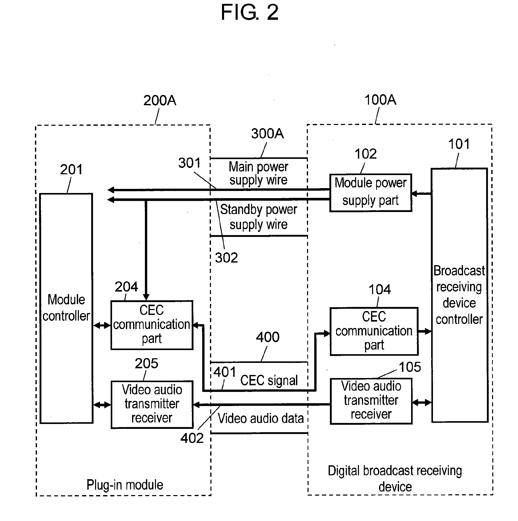
[0055]FIG. 2 is a block diagram of a digital broadcast receiving device and a plug-in module of the video display system in the first preferred embodiment of the present invention. In FIG. 2, digital broadcast receiving device 100A, plug-in module 200A, and module connecting cable 300A and HDMI cable 400 for connecting digital broadcast receiving device 100A to plug-in module 200A are shown, in which the configuration of a portion for each connecting function and the connecting wire between the both are shown. As to digital broadcast receiving device 100A, digital television broadcast that is a representative example is described in the following with respect to a television receiver for signal reception, demodulation, and display.

[0056]Video audio data transmission and reception between digital broadcast receiving device 100A and plug-in module 200A, and control between the both are executed via HDMI cable 400 that is a connecting cable. HDMI cable 400, television receivers, and vi...

second preferred embodiment

[0063]FIG. 3 is a block diagram of a digital broadcast receiving device and a plug-in module of the video display system in the second preferred embodiment of the present invention. Shown in FIG. 3 is a configuration formed by adding function block for authentication and signal line to the configuration shown in FIG. 2. For authentication of plug-in module 200B, authentication part 103 and authentication part 203 are respectively installed in digital broadcast receiving device 100B and plug-in module 200B, and equipment authentication is executed via authentication secure communication wire 303 which is encrypted and installed in module connecting cable 300B.

[0064]Authentication part 103 is an example of first authentication part for equipment authentication. Authentication part 203 is an example of second authentication part for equipment authentication. HDMI also includes authentication function, but it is HDCP (High-bandwidth Digital Content Protection system) authentication limi...


PUM


Abstract

It provides a video display system capable of effective control of power consumption, safe power-off operation, and resetting from a hang-up state by properly setting power supply to a plug-in module in accordance with the operational request and operational status of a digital broadcast receiving device and the plug-in module, a display device, a plug-in module, and a plug-in module power control method. Each of the digital broadcast receiving device and plug-in module includes an authentication part for equipment authentication thereof, CEC communication part for control signal communication, and a video audio transmitter receiver. The digital broadcast receiving device serves for switching the module power supply part for power supply to the plug-in module from standby power to main power in accordance with the control signal after equipment authentication is obtained for the plug-in module.

Description

TECHNICAL FIELD[0001]The present invention relates to a video display system comprising an externally installed plug-in module having specified communication function and information processing function which is externally connected to a display device, a display device, a plug-in module, and a power control method of the plug-in module.BACKGROUND ART[0002]Recently, digital broadcast receiving devices compatible with ground digital broadcast and BS digital broadcast are rapidly becoming higher in performance with enhancement of picture quality and enlargement of screen size. Internet connecting function, recording function interlocked with broadcast programs, and decoding function for charged broadcast reception can be mentioned as representative ones.[0003]On the other hand, such additional functions are faster in technical innovation as compared with broadcast program audio-video function that is the essential function of a digital broadcast receiving device. Accordingly, there is...

Claims


Application Information

Patent Timeline
IPC IPC(8): G06F1/26G06F21/00H04N5/44
CPCG09G5/006G09G2370/12H04N21/4436H04N5/63H04N21/43635H04N5/4403H04N21/42204
Inventor OKUDA, SACHIKOMIYAJIMA, SUSUMUYANAGIMICHI, TOYOKAZUSUZUKI, HIDEKAZU
Owner PANASONIC CORP
Learn More