
Radiographic image capturing apparatus, biopsy apparatus, radiographic image capturing method, and biopsy method

a radiographic image and apparatus technology, applied in the field of radiographic image capture apparatus, biopsy apparatus, radiographic image capture method, biopsy method, etc., can solve the problem of objects to be examined being exposed to unwanted radiation

Inactive Publication Date: 2010-09-30
FUJIFILM CORP
View PDF6 Cites 13 Cited by
  • Summary
  • Abstract
  • Description
  • Claims
  • Application Information

AI Technical Summary

Benefits of technology

[0011]It is an object of the present invention to make it possible to change the image capturing angle of a radiation source in a stereographic image capturing process depending on an object to be examined and also to prevent the object to be examined from being exposed to unwanted radiations.
[0016]According to the present invention, as described above, the image capturing angle of the radiation source in the stereographic image capturing process is changed based on the positional information of the object to be examined. Therefore, the image capturing angle of the radiation source in the stereographic image capturing process can be changed based on the object to be examined, and the object to be examined is prevented from being exposed to unwanted radiations.

Problems solved by technology

If the stereographic image capturing process is carried out while the biopsy region is placed out of the examinable area, then the object to be examined is exposed to unwanted radiations.
However, the thus-fixed examinable area for the object having the larger thickness may be too narrow for an object to be examined which has a smaller thickness, so that the biopsy region in the object having the smaller thickness may fall out of the examinable area.

Method used


Image

  • Radiographic image capturing apparatus, biopsy apparatus, radiographic image capturing method, and biopsy method
  • Radiographic image capturing apparatus, biopsy apparatus, radiographic image capturing method, and biopsy method
  • Radiographic image capturing apparatus, biopsy apparatus, radiographic image capturing method, and biopsy method

Examples


Embodiment Construction

[0026]A radiographic image capturing apparatus and a biopsy apparatus according to an embodiment of the present invention in relation to a radiographic image capturing method and a biopsy method carried thereby will be described below with reference to the drawings.

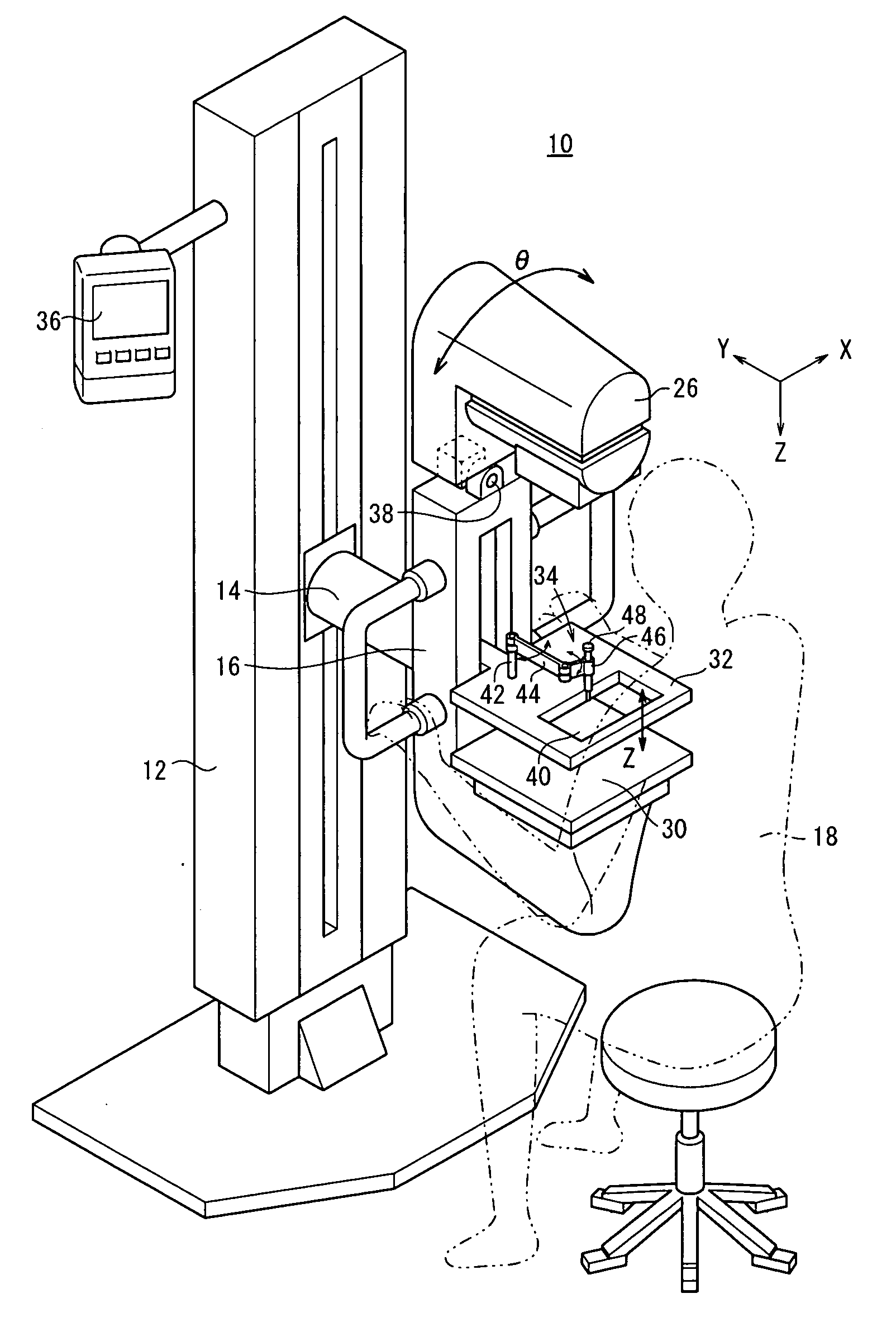
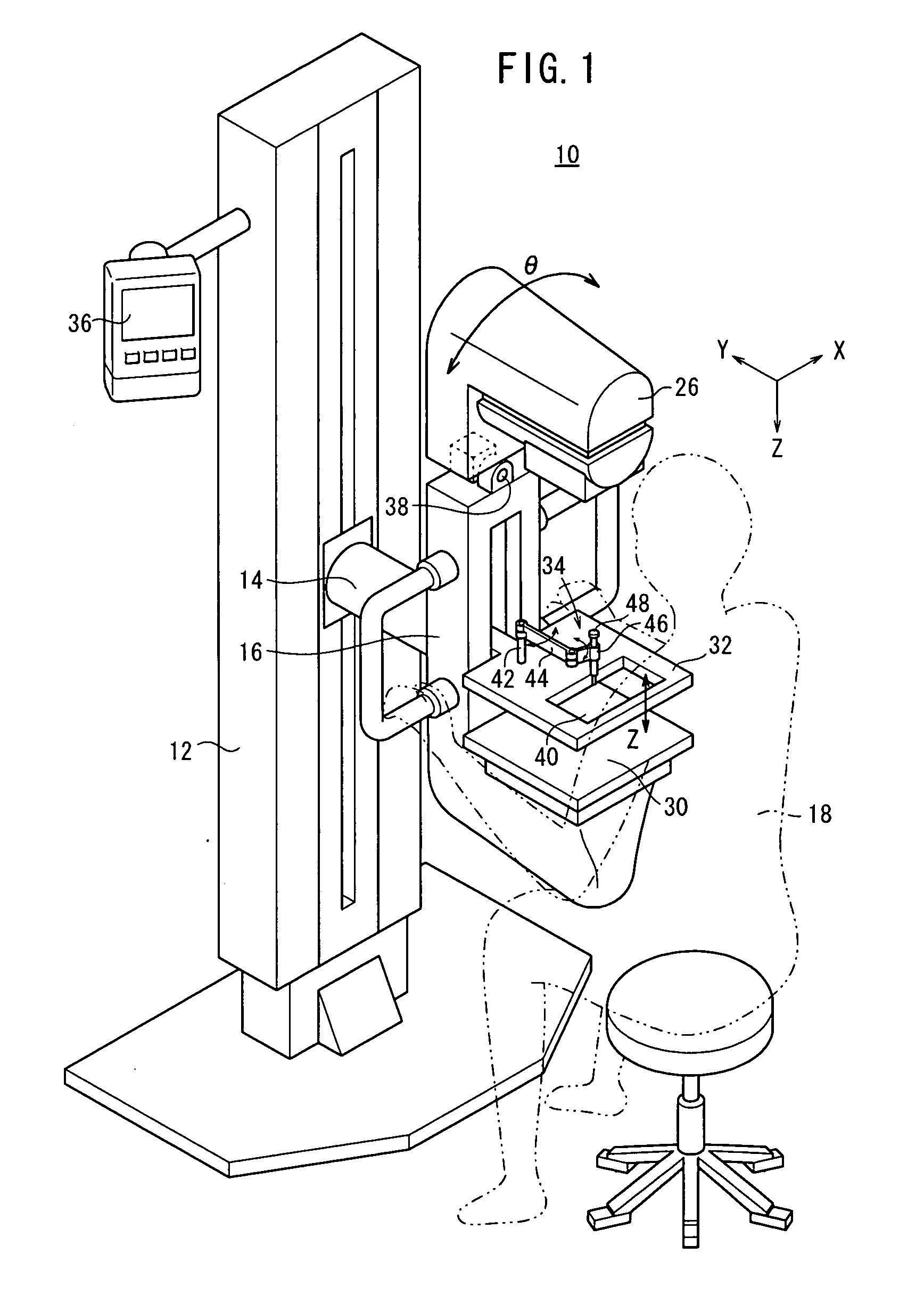
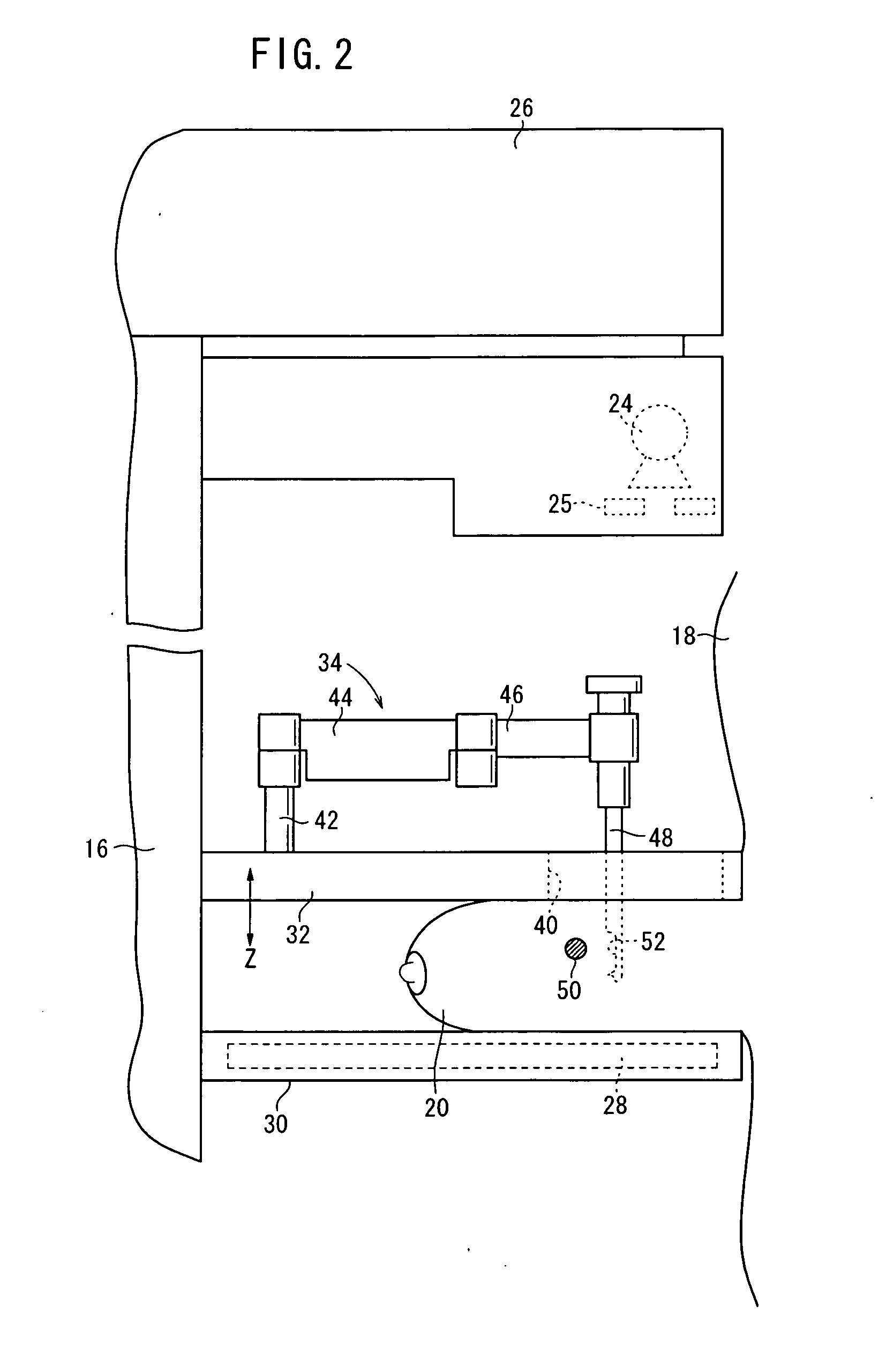
[0027]FIG. 1 shows a mammographic apparatus 10 serving as radiographic image capturing apparatus or a breast image capturing apparatus according to the embodiment of the present invention. As shown in FIG. 1, the mammographic apparatus 10 includes an upstanding base 12, a vertical arm 16 fixed to a horizontal swing shaft 14 disposed substantially centrally on the base 12, a radiation source housing unit 26 housing therein a radiation source 24 (see FIGS. 2 and 3) for applying radiation 22 (see FIG. 3) to a breast 20 (an object to be examined, see FIG. 3) of a subject 18, and which is fixed to an upper end of the arm 16, an image capturing base 30 mounted on a lower end of the arm 16 and housing therein a solid-state detec...


PUM


Abstract

A radiographic image capturing apparatus includes a radiation source for applying a radiation to an object to be examined, a radiation detector for detecting the radiation which has passed through the object and converting the detected radiation into a radiographic image, a positional information acquiring unit for acquiring positional information of the object, and an image capturing angle changer for changing an image capturing angle of the radiation source with respect to the radiation detector based on the positional information in a stereographic image capturing process for capturing at least two radiographic images of the object by applying the radiation to the object from directions which are different from each other.

Description

CROSS-REFERENCE TO RELATED APPLICATION[0001]This application is based upon and claims the benefit of priority from Japanese Patent Application No. 2009-086245 filed on Mar. 31, 2009, of which the contents are incorporated herein by reference.BACKGROUND OF THE INVENTION[0002]1. Field of the Invention[0003]The present invention relates to a radiographic image capturing apparatus and a radiographic image capturing method for capturing at least two radiographic images of an object to be examined by irradiating the object with a radiation from directions which are different from each other.[0004]The present invention is also concerned with a biopsy apparatus and a biopsy method for calculating the three-dimensional position of a region to be biopsied (hereinafter referred to as “biopsy region”) of the object based on the two radiographic images, moving a biopsy needle to the biopsy region based on the calculated three-dimensional position, and removing a tissue sample from the biopsy reg...

Claims


Application Information

Patent Timeline
IPC IPC(8): A61B10/02A61B6/02
CPCA61B6/12A61B6/502A61B10/0275A61B10/0283A61B6/0478A61B2019/205A61B2019/5227A61B2019/5238A61B6/022A61B19/201A61B90/11A61B90/17A61B2090/371A61B2090/376
Inventor NAKAYAMA, HIROKI
Owner FUJIFILM CORP
Learn More