Eureka AIR delivers breakthrough ideas for toughest innovation challenges, trusted by R&D personnel around the world.

Resolution Scalable View Projection

a technology of light transport matrix and projection screen, which is applied in the direction of pulse technique, television system, instruments, etc., can solve the problems of loss of captured images pertaining to some projector pixels, and achieve the effect of simplifying the generation of transport matrix

Inactive Publication Date: 2010-09-30
SEIKO EPSON CORP
View PDF40 Cites 97 Cited by
  • Summary
  • Abstract
  • Description
  • Claims
  • Application Information

AI Technical Summary

Benefits of technology

[0035]Application of dual photography is simplified by reducing the number of captured images needed to generate a light transport matrix T of (p×q) projector pixel array from (p×q) images to (p+q) images. Manipulation of the light transport matrix T is simplified by replacing the use of a fully populated light transport matrix T with an index associating each projector pixel to only non-zero light transport coefficient values. By eliminating the use of zero-valued light transport coefficients, the memory and processing requirements for implementing dual photography are greatly reduced. This dual photography technique is applied to the calibration of projector-camera systems.
[0037]To further expand its use, the light transport matrix is scanned along a row, and only the brightest non-zero values are retained. All other value entries in the row are preferably set to zero. This method facilitates the creation of the inverse of the light transport matrix, but introduces problems when the resolution of the camera is close to, or smaller than, the resolution of the projector. Since the number of camera pixels is lower than the number of projector pixels, it is very likely that a single projector pixel may be captured by multiple camera pixels. Since only the brightest captured value is kept along a row of the light transport matrix, it is likely that captured images pertaining to some of the projector pixels will be lost, i.e. erased or set to zero values. It is therefore necessarily to create new images for the missing projector pixels.

Problems solved by technology

This method facilitates the creation of the inverse of the light transport matrix, but introduces problems when the resolution of the camera is close to, or smaller than, the resolution of the projector.
Since only the brightest captured value is kept along a row of the light transport matrix, it is likely that captured images pertaining to some of the projector pixels will be lost, i.e. erased or set to zero values.

Method used


Image

  • Resolution Scalable View Projection
  • Resolution Scalable View Projection
  • Resolution Scalable View Projection

Examples


Embodiment Construction

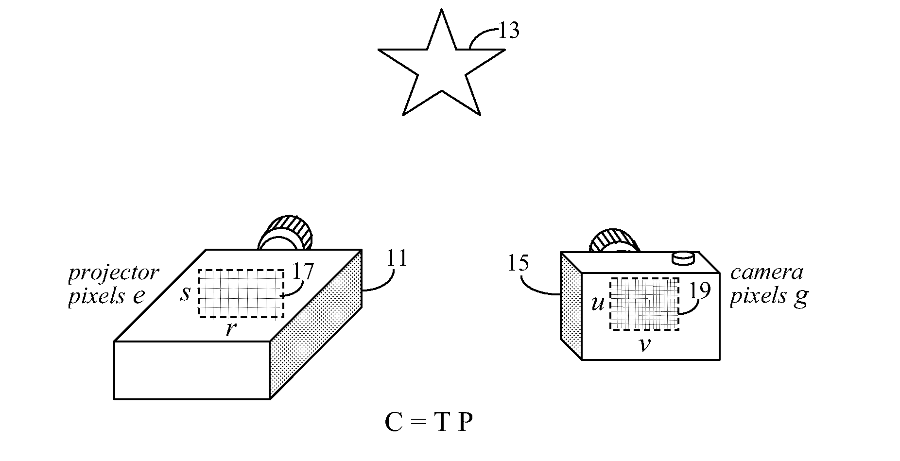
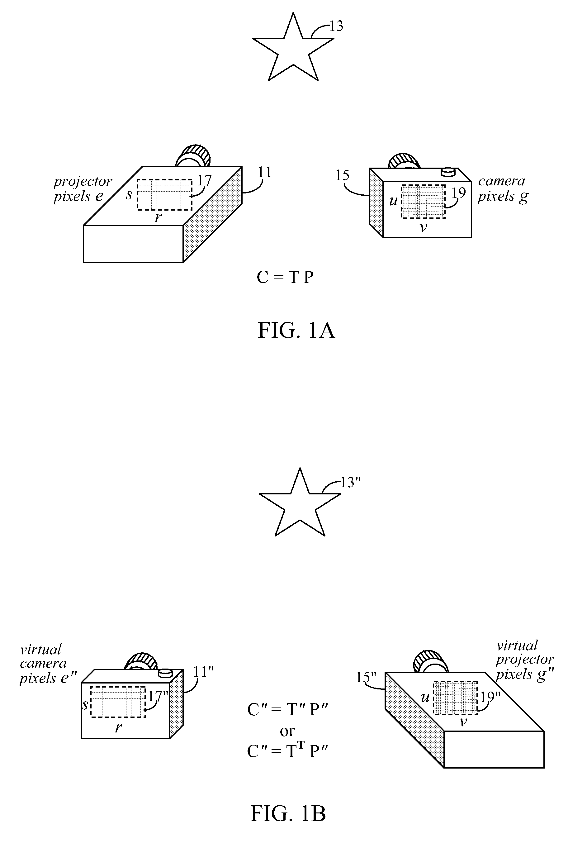
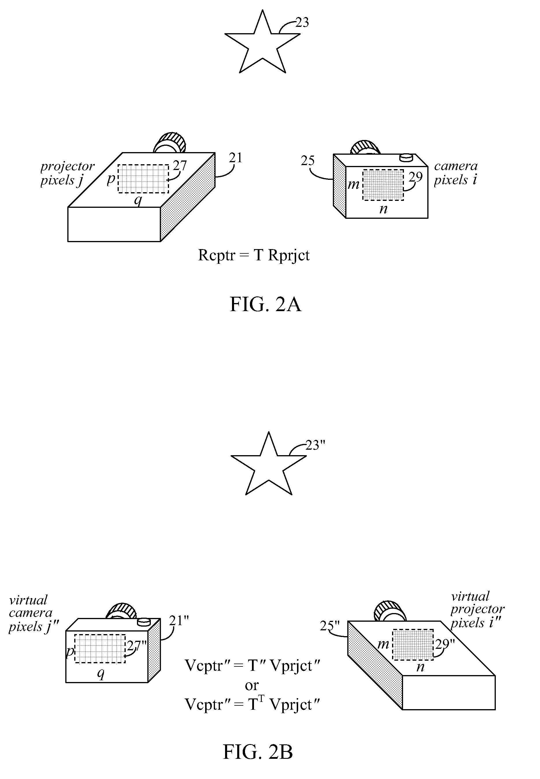
[0117]In order to apply camera calibration techniques to projectors, one would require projectors to be able to capture images. That is, if projectors could capture images, then projector-camera systems could be treated like multi-camera systems, and standard camera calibration techniques (described above) might be used to calibrate projector-camera systems. In other words, if a projector could be treated as a pseudo-camera, then it could be calibrated along with a real camera in a manner similar to the camera calibration stage of the multi-camera system described above, and the “bootstrappingprojector calibration stage previously used for calibrating projector-camera systems might be eliminated.

[0118]With reference to FIG. 2A, an imaging setup in accord with the present invention may include a real projector 21 and a real camera 25. Real projector 21 is preferably a digital projector and has an imaging element including an imaging projection array (i.e. projector pixel array 27),...


PUM


Abstract

A projection system uses a transformation matrix to transform a projection image p in such a manner so as to compensate for surface irregularities on a projection surface. The transformation matrix makes use of properties of light transport relating a projector to a camera. If the resolution a camera is lower than that of a projector within said projection system, then the transformation matrix will have holes where image data corresponding to a projector pixel will have been lost. In this, case, new image are generated to fill-in the holes.

Description

BACKGROUND[0001]1. Field of Invention[0002]The present invention is related to a method of generation a light transport matrix T in a projector-camera system where the resolution of the camera is not greater than that of the projector.[0003]2. Description of the Related Art[0004]When projectors and cameras are combined, hybrid devices and systems that are capable of both projecting and capturing light are born. This emerging class of imaging devices and systems are known in the research community as projector-camera systems. Typically, images captured by one or more cameras, are used to estimate attributes about display environments, such as the geometric shapes of projection surfaces. The projectors in these projector-camera systems then adapt their projected images so as to compensate for shape irregularities in the projection surfaces to improve the resultant imagery. In other words, by using a camera, a projector can “see” distortions in a projected image, and then adjust its pr...

Claims


Application Information

Patent Timeline
Patent Type & Authority Applications(United States)
IPC IPC(8): H04N5/74
CPCH04N9/3147H04N9/3197H04N9/3194H04N9/3185
Inventor XIAO, JINGTAN, KAR-HAN
Owner SEIKO EPSON CORP
Why Eureka
Eureka Blog
Learn More