
Method and Device for Coding Transition Frames in Speech Signals

a transition frame and speech signal technology, applied in the field of digitally encoding a sound signal, can solve the problems of frame erasure concealment, transmission errors, and very annoying perceptual impact, and achieve the effect of improving coding efficiency and improving encoder robustness against lost frames

Active Publication Date: 2010-09-23
VOICEAGE EVS LLC
View PDF17 Cites 36 Cited by
  • Summary
  • Abstract
  • Description
  • Claims
  • Application Information

AI Technical Summary

Benefits of technology

[0009]An object of the present invention is therefore to provide a method and device for encoding transition frames in a predictive speech and / or audio encoder in order to improve the encoder robustness against lost frames and / or improve the coding efficiency.
[0010]Another object of the present invention is to eliminate error propagation and increase coding efficiency in CELP-based codecs by replacing the inter-frame dependent adaptive codebook search by a non-predictive, for example glottal-shape, codebook search. This technique requires no extra delay, negligible additional complexity, and no increase in bit rate compared to traditional CELP encoding.SUMMARY OF THE INVENTION

Problems solved by technology

A problem of strong prediction inherent in CELP-based speech coders appears in presence of transmission errors (erased frames or packets) when the state of the encoder and the decoder become desynchronized.
Naturally, the perceptual impact can be very annoying.
Transitions from unvoiced speech segment to voiced speech segment (e.g. transition between a consonant or a period of inactive speech, and a vowel) or transitions between two different voiced segments (e.g. transitions between two vowels) are the most problematic cases for frame erasure concealment.
Again, as the decoder usually conceals the lost frame with the use of the past frame information, the state of the encoder and the decoder will be very different, and the synthesized signal can suffer from important distortion.

Method used


Image

  • Method and Device for Coding Transition Frames in Speech Signals
  • Method and Device for Coding Transition Frames in Speech Signals
  • Method and Device for Coding Transition Frames in Speech Signals

Examples


Embodiment Construction

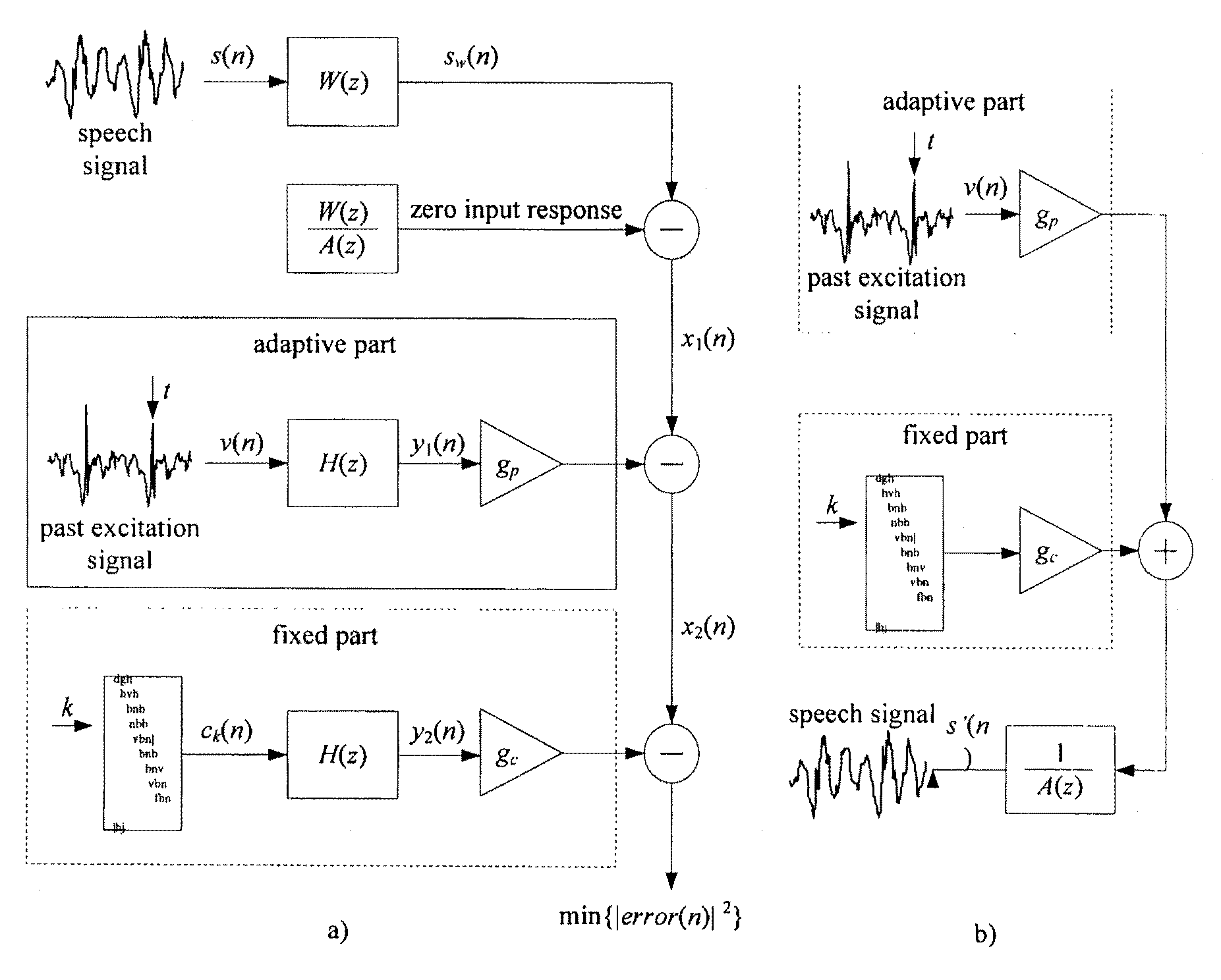
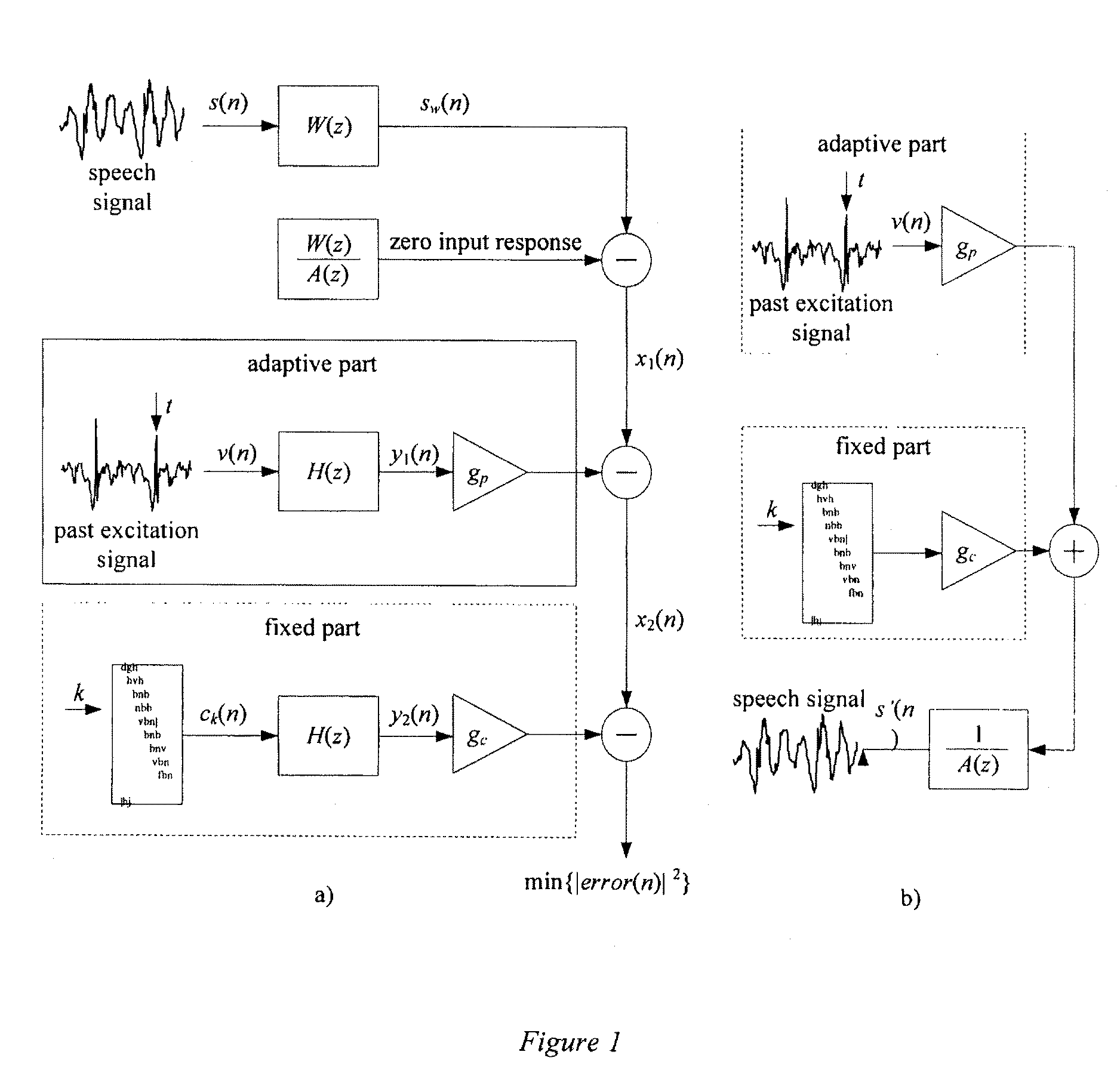
[0052]The non-restrictive illustrative embodiment of the present invention is concerned with a method and device whose purpose is to overcome error propagation in the above described situations and increase the coding efficiency.

[0053]More specifically, the method and device according to the non-restrictive illustrative embodiment of the present invention implement a special encoding, called transition mode (TM) encoding technique, of transition frames and frames following the transition in a sound signal, for example a speech or audio signal. The TM coding technique replaces the adaptive codebook of the CELP codec by a new codebook of glottal impulse shapes, hereinafter designated as glottal-shape codebook, in transition frames and in frames following the transition. The glottal-shape codebook is a fixed codebook independent of the past excitation. Consequently, once a frame erasure is over, the encoder and the decoder use the same excitation whereby convergence to clean-channel sy...


PUM


Abstract

There is provided a transition mode device and method for use in a predictive-type sound signal codec for producing a transition mode excitation replacing an adaptive codebook excitation in a transition frame and / or a frame following the transition in the sound signal, comprising an input for receiving a codebook index and a transition mode codebook for generating a set of codevectors independent from past excitation. The transition mode codebook is responsive to the index for generating, in the transition frame and / or frame following the transition, one of the codevectors of the set corresponding to the transition mode excitation. There is also provided an encoding device and method and a decoding device and method using the above described transition mode device and method.

Description

FIELD OF THE INVENTION[0001]The present invention relates to a technique for digitally encoding a sound signal, for example a speech or audio signal, in view of transmitting and synthesizing this sound signal.[0002]More specifically, but not exclusively, the present invention relates a method and device for encoding transition frames and frames following the transition in a sound signal, for example a speech or audio signal, in order to reduce the error propagation at the decoder in case of frame erasure and / or to enhance coding efficiency mainly at the beginning of voiced segments (onset frames). In particular, the method and device replace the adaptive codebook typically used in predictive encoders by a codebook of, for example, glottal impulse shapes in transition frames and in frames following the transition. The glottal-shape codebook can be a fixed codebook independent of the past excitation whereby, once the frame erasure is over, the encoder and the decoder use the same exci...

Claims


Application Information

Patent Timeline
IPC IPC(8): G10L19/04
CPCG10L19/12G10L19/08G10L15/02G10L19/09
Inventor EKSLER, VACLAVJELINEK, MILANSALAMI, REDWAN
Owner VOICEAGE EVS LLC
Learn More