
Joint high dynamic range compression and noise reduction

a high dynamic range and noise reduction technology, applied in image analysis, image enhancement, instruments, etc., can solve the problems of increasing noise levels and introducing artifacts, and achieve the effect of lowering noise and high computational efficiency

Inactive Publication Date: 2010-09-23
SONY CORP +1
View PDF2 Cites 14 Cited by
  • Summary
  • Abstract
  • Description
  • Claims
  • Application Information

AI Technical Summary

Benefits of technology

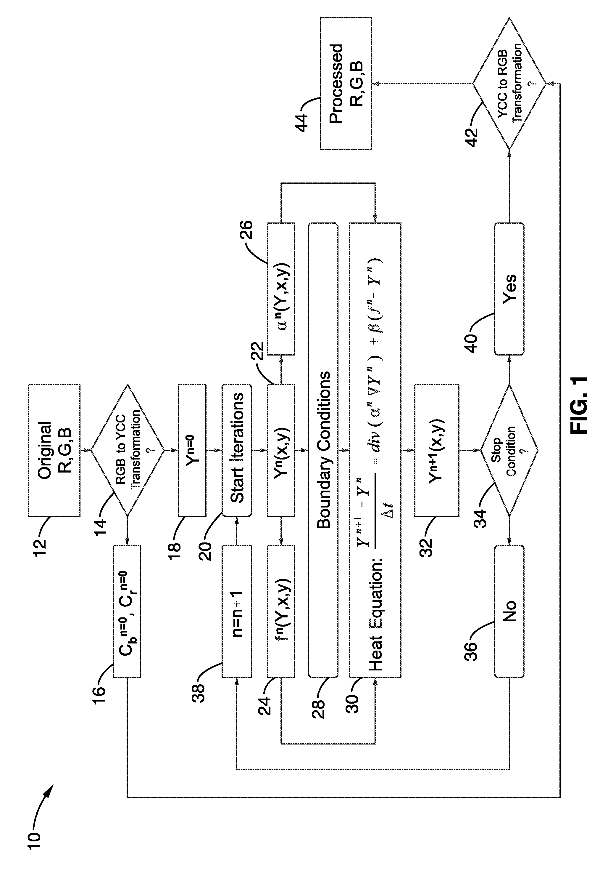
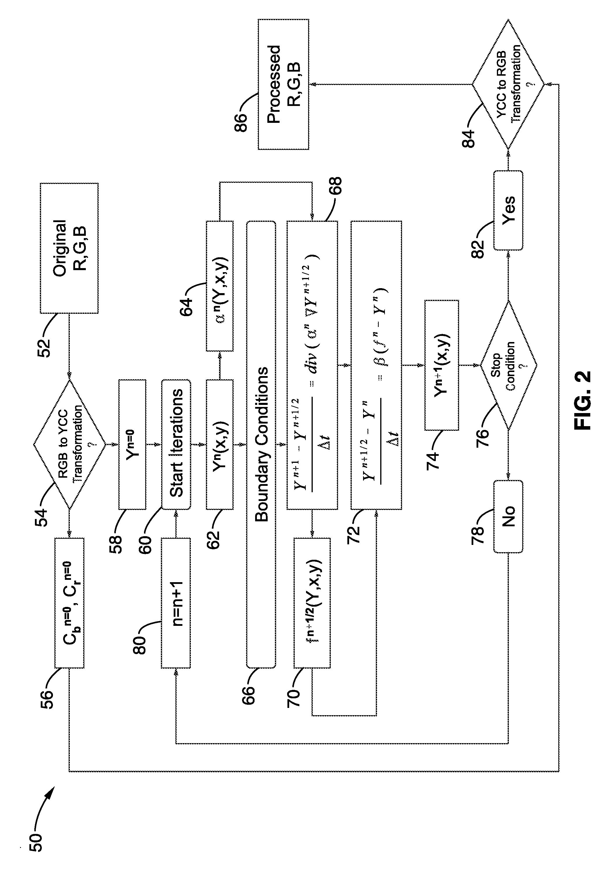
[0013]The present invention may be applied in different ways and to different components in different color spaces. In addition, one of ordinary skill in the art will appreciate that modifications on the use of the heat equation can be applied without departing from the teachings of the present invention. For example, the heat equation can be utilized with different terms applied to different color channels at different points within the signal processing pipeline. For example, in digital cameras the signal is usually transferred from RGB to YCC, wherein an implementation of the present invention can be applied twice—once after RGB signal acquisition, and a second time after conversion to YCC. It can also be applied not only to Y but to Cb, Cr in order to compensate for potential color shift and to reduce the chrominance noise. Furthermore, additional terms can be added to the heat equation without departing from the teachings of the present invention, thereby potentially addressing extra problems or as an aid in solving joint high-dynamic range (HDR) and noise reduction (NR) problem. One example discussed herein adds another term with a different diffusion coefficient to aid improved calculation accuracy for the heat source.
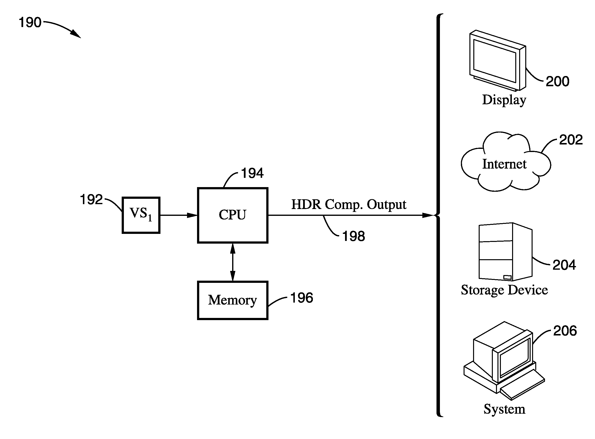
[0025]Another aspect of the invention is to process the image signals with lowered noise and high computational efficiency when combining the HDR compression and NR.

Problems solved by technology

Noise reduction is of particular concern with regard to high dynamic range compression because brightening of dark areas during high dynamic range compression has the potential to increase noise levels and introduce artifacts.

Method used


Image

  • Joint high dynamic range compression and noise reduction
  • Joint high dynamic range compression and noise reduction
  • Joint high dynamic range compression and noise reduction

Examples


Embodiment Construction

[0041]Referring more specifically to the drawings, for illustrative purposes the present invention is embodied in the apparatus generally shown in FIG. 1 through FIG. 11. It will be appreciated that the apparatus may vary as to configuration and as to details of the parts, and that the method may vary as to the specific steps and sequence, without departing from the basic concepts as disclosed herein.

1. INTRODUCTION

[0042]The method and apparatus of the invention simultaneously performs high dynamic range compression and noise reduction on an imaging input. It will be appreciated that noise considerations are very important when performing high dynamic range compression, as brightening of dark areas during the high dynamic range compression process often leads to increased levels of noise. Performing the simultaneous noise reduction coupled with high dynamic range compression provides unexpectedly benefits with regard to noise reduction in comparison with performing the techniques se...


PUM


Abstract

A high dynamic range (HDR) compression method and apparatus modeled after the heat equation describing temperature changes in a thin plate. This approach allows combining high dynamic range compression together with noise reduction in a single process, to be performed within the same iteration of the heat equation. Noise reduction is of particular concern while performing HDR compression because brightening of dark areas during high dynamic range compression has the potential to increase noise levels. Performing image processing techniques in combination according to the invention provides enhanced results while lowering the overall processing overhead. This innovation extends the heat equation analogy by adding anisotropic diffusion as an additional term, which allows joint operation of HDR and NR and mitigates noise enhancement within HDR compression during shadow enhancement.

Description

CROSS-REFERENCE TO RELATED APPLICATIONS[0001]Not ApplicableSTATEMENT REGARDING FEDERALLY SPONSORED RESEARCH OR DEVELOPMENT[0002]Not ApplicableINCORPORATION-BY-REFERENCE OF MATERIAL SUBMITTED ON A COMPACT DISC[0003]Not ApplicableNOTICE OF MATERIAL SUBJECT TO COPYRIGHT PROTECTION[0004]A portion of the material in this patent document is subject to copyright protection under the copyright laws of the United States and of other countries. The owner of the copyright rights has no objection to the facsimile reproduction by anyone of the patent document or the patent disclosure, as it appears in the United States Patent and Trademark Office publicly available file or records, but otherwise reserves all copyright rights whatsoever. The copyright owner does not hereby waive any of its rights to have this patent document maintained in secrecy, including without limitation its rights pursuant to 37 C.F.R. § 1.14.BACKGROUND OF THE INVENTION[0005]1. Field of the Invention[0006]This invention per...

Claims


Application Information

Patent Timeline
IPC IPC(8): G09G5/02G06K9/36G06V10/30
CPCG06K9/40G06T2207/20208G06T5/009G06T5/002G06V10/30G06T5/92G06T5/70
Inventor CIUREA, FLORIANBERESTOV, ALEXANDER
Owner SONY CORP
Learn More