
Voice coil motor with surface coil

Active Publication Date: 2010-09-23
VASSTEK INT
View PDF5 Cites 30 Cited by
  • Summary
  • Abstract
  • Description
  • Claims
  • Application Information

AI Technical Summary

Benefits of technology

[0009]One of the primary objectives of the present invention is to form a surface coil of a patterned metal layer of a VCM, which saves space usually occupied by copper coils, thereby avoiding an over-large volume.
[0010]One of the secondary objectives of the present invention is to form a surface coil of a patterned metal layer of the VCM and traces required by a Hall sensor (for transmitting operation voltages and feedback sensing signals) and place the Hall sensor in one of the set of sensing elements to simultaneously form the surface coil and the traces, which saves on fabrication costs as well as space usually occupied by copper coils and avoids an over-large volume.
[0011]Another of the secondary objectives of the present invention is to set a groove on a side of the magnetic sensing element facing the surface coil, wherein the groove is large enough for the Hall sensor to fit between one of the set of the magnetic sensing elements and the surface coil, which reduces an overall volume and thereby avoids an over-large volume due to the Hall sensor.
[0013]To realize the objectives mentioned above, the present invention further provides a VCM with a surface coil, characterized in that the VCM includes: a set of magnetic sensing elements, a lens carrier which is physically connected to the set of magnetic sensing elements and carries a lens, a pedestal, a set of printed circuit boards which are fixed onto the pedestal, a set of surface coil which is formed by a patterned metal layer on the set of the printed circuit board and faces the set of magnetic sensing elements respectively, and a sensing element which is set in one of the set of printed circuit boards and is for transmitting signals via a trace formed on the set of printed circuit boards, wherein the sensing element is placed between the set of magnetic sensing elements and the surface coil, the sensing element senses a variation in a magnetic field resulting from the motion of the set of magnetic sensing elements to determine a motion status of the lens carrier. The pedestal and a plurality of guide posts are formed in one piece. Furthermore, there are at least two guide posts set onto the pedestal symmetrically. In addition, an interaction between the surface coil supplied with power and a main magnetic flux provided by the set of magnetic sensing elements makes the lens carrier move in a straight line along a direction of the guide posts. A patterned metal layer is fabricated on the set of printed circuit boards to form the surface coil, and a Hall sensor is installed in one of the printed circuit boards and transmits signals (e.g., operation voltages and feedback sensing signals) via traces fabricated on the set of printed circuit boards, so as to achieve fabricating the surface coil and traces simultaneously, saving space which is usually occupied by copper coils. The Hall sensor can sense a variation in a magnetic field resulting from the motion of the set of magnetic sensing elements to determine a motion status of the lens carrier.

Problems solved by technology

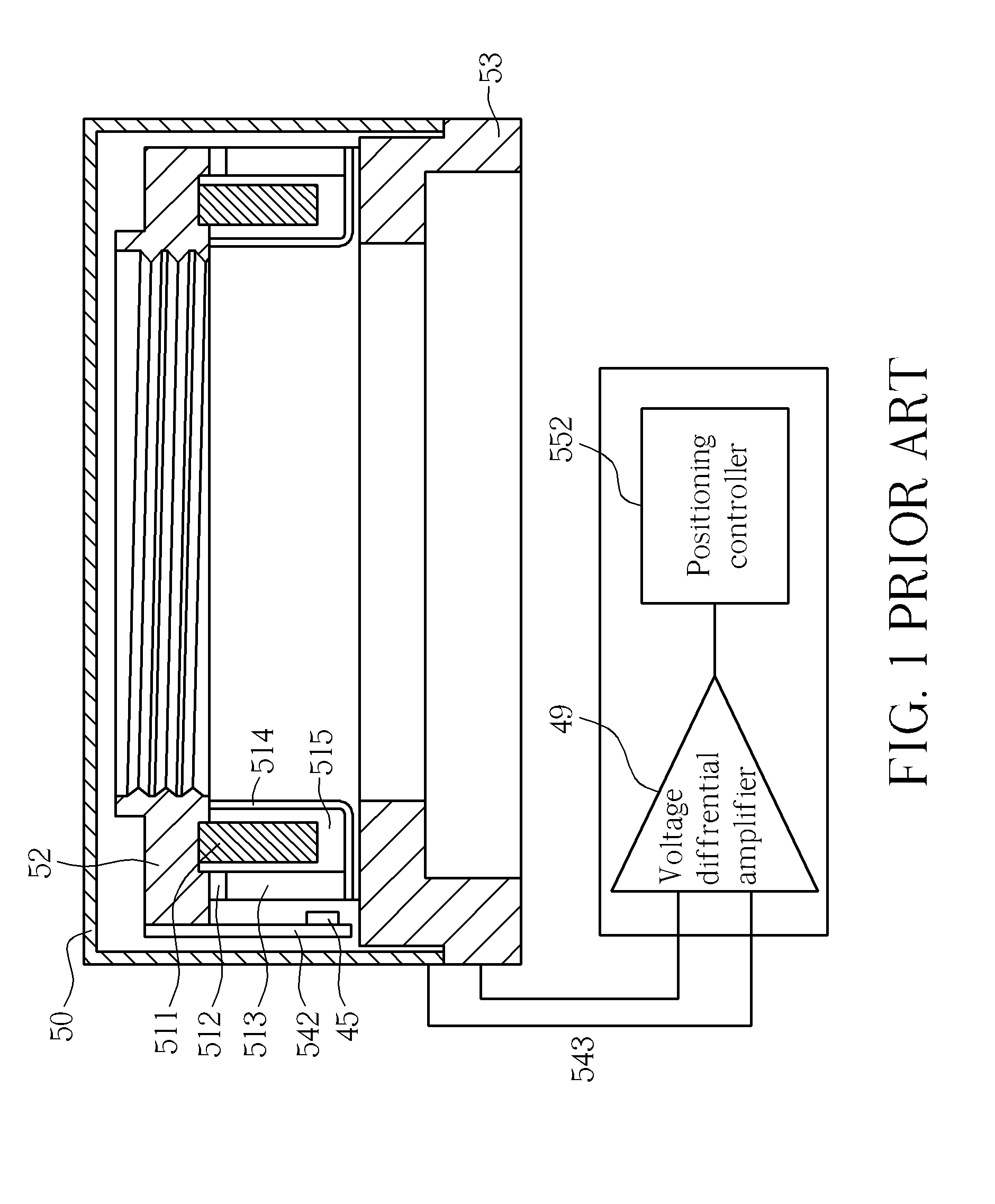
However, since a space occupied by the copper coil of the moving coil 511 is large, the volume of the conventional VCM is inevitably huge.
In order to utilize the Hall sensor 45 to act as a sensing element of feedback signals, traces on the PCB 542 must be routed to transmit operation voltages and feedback sensing signals, which not only increases fabrication and assembly costs, but also increases the complexity of an element structural design inside the VCM.

Method used


Image

  • Voice coil motor with surface coil
  • Voice coil motor with surface coil
  • Voice coil motor with surface coil

Examples


Embodiment Construction

[0019]The following further describes the present invention in detail in conjunction with various figures and embodiments.

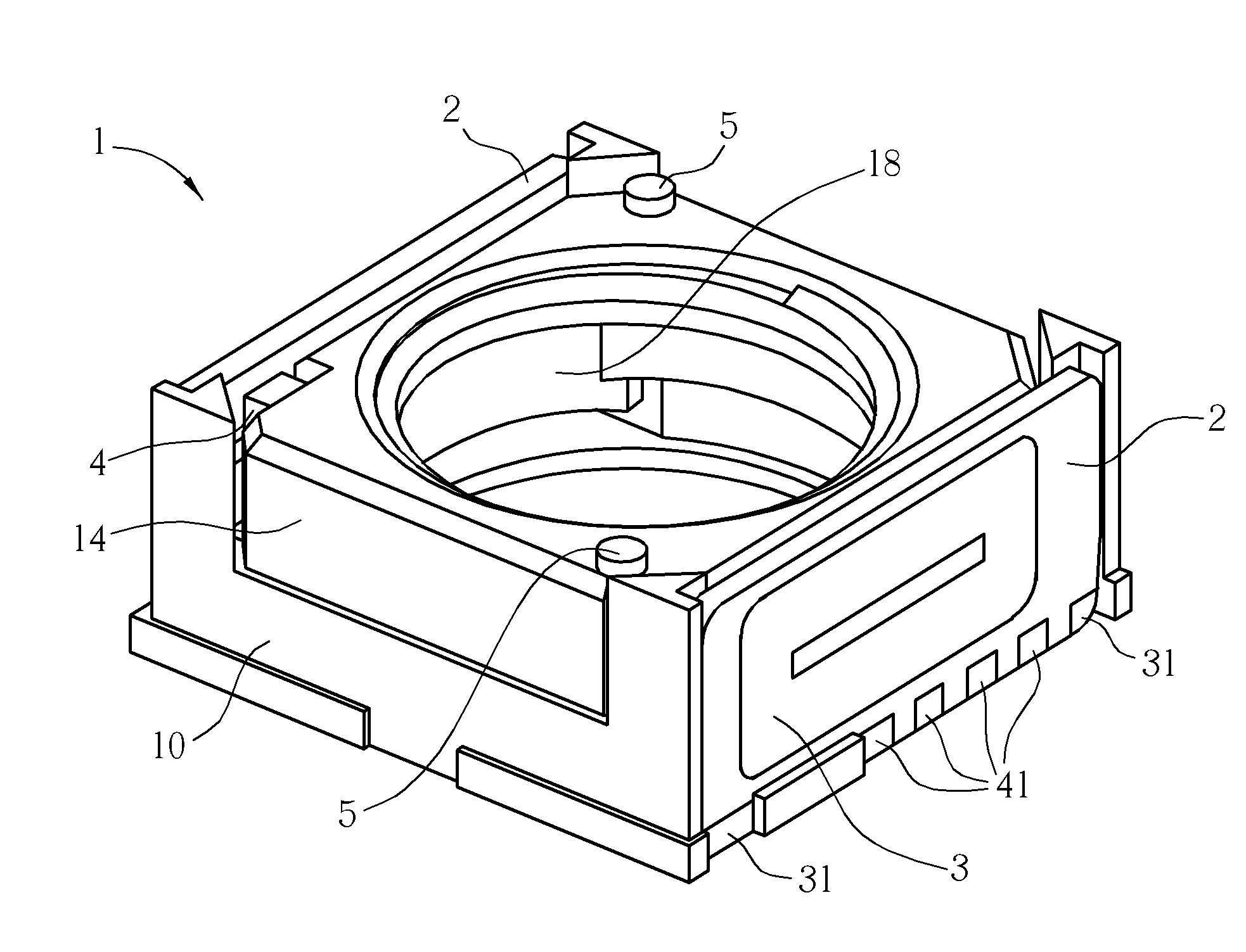
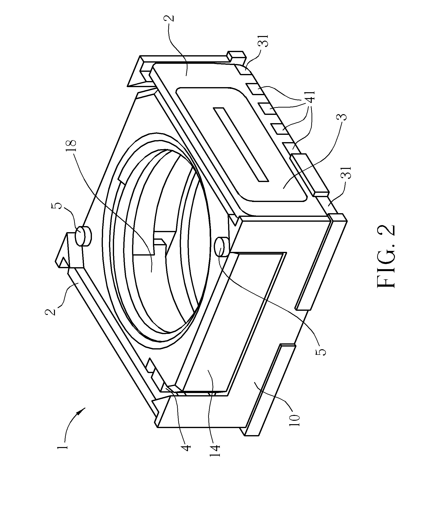
[0020]Please refer to FIG. 2, which is a diagram of a VCM according to the present invention. As shown in FIG. 2, a VCM 1 with a surface coil includes: a set of magnetic sensing elements 18, a lens carrier 14 physically connected to the set of magnetic sensing elements 18, a pedestal 10, a set of printed circuit boards 2 which is fixed onto the pedestal 10, and a surface coil 3. The lens carrier 14 is for carrying a lens (which is not illustrated in the figure). The pedestal 10 and a plurality of guide posts 5 are monolithically formed in one piece, and at least two guide posts 5 are set onto the pedestal 10. The lens carrier 14 has a plurality of holes for the guide posts to fit in.

[0021]The surface coil 3 is formed on the set of printed circuit boards 2, thereby saving space occupied by copper coils and avoiding an over-large volume.

[0022]Considering the cost f...


PUM


Abstract

A voice coil motor with a surface coil includes a set of magnetic sensing elements, a lens carrier physically connected to the set of magnetic sensing elements, a pedestal, and a set of printed circuit boards fixed onto the pedestal. A patterned metal layer is fabricated on the set of printed circuit boards to form the surface coil, a Hall sensor is installed on one of the printed circuit boards and transmits signals (e.g., operation voltages and feedback sensing signals) via traces fabricated on the set of printed circuit boards, so as to achieve simultaneous fabrication of the surface coil and traces, thereby saving space which is conventionally occupied by copper coils. The Hall sensor can sense a variation in a magnetic field resulting from the motion of the set of magnetic sensing elements to determine a motion status of the lens carrier.

Description

BACKGROUND OF THE INVENTION[0001]1. Field of the Invention[0002]The present invention relates to a voice coil motor, and more particularly, to a voice coil motor with a surface coil.[0003]2. Description of the Prior Art[0004]In order to perform a more accurate position control for a set of lenses or an access arm of a hard disk drive, a voice coil motor (VCM) is adopted to move the set of lenses or the access arm of the hard disk drive. The structure of a VCM is primarily a coil placed within a magnetic circuit including a permanent magnet.[0005]In an optical system employing a VCM, a distance at which a set of lenses is moved corresponds to a current flowing through a coil; therefore, when a VCM is utilized to implement the optical zoom functionality, an accurate control can be easily achieved by applying a specific current value. For example, Taiwanese Patent Application No. 1239432 (U.S. Patent Publication No. 2006 / 0055252), entitled “VOICE COIL MOTOR APPARATUS FOR POSITIONING”, ...

Claims


Application Information

Patent Timeline
IPC IPC(8): H02K41/03G01R33/00
CPCG02B7/022H02K41/0356G02B7/023H02K33/18G02B7/04
Inventor TSAI, CHUO-HANLEE, SHIH-CHUAN
Owner VASSTEK INT
Learn More