
Plasma generating apparatus, plasma generating method and remote plasma processing apparatus

a plasma generating apparatus and plasma technology, applied in the direction of electric discharge tubes, chemical vapor deposition coatings, coatings, etc., can solve the problems of increasing the risk of coolant tube breakage, the gas excitation portion cannot be sufficiently cooled down, and the plasma excitation efficiency is difficult to achieve, etc., to achieve the effect of improving plasma excitation efficiency, microwave transmission and radiation efficiency, and reducing the size of the plasma generating apparatus

Inactive Publication Date: 2010-09-09
TOKYO ELECTRON LTD
View PDF23 Cites 110 Cited by
  • Summary
  • Abstract
  • Description
  • Claims
  • Application Information

AI Technical Summary

Benefits of technology

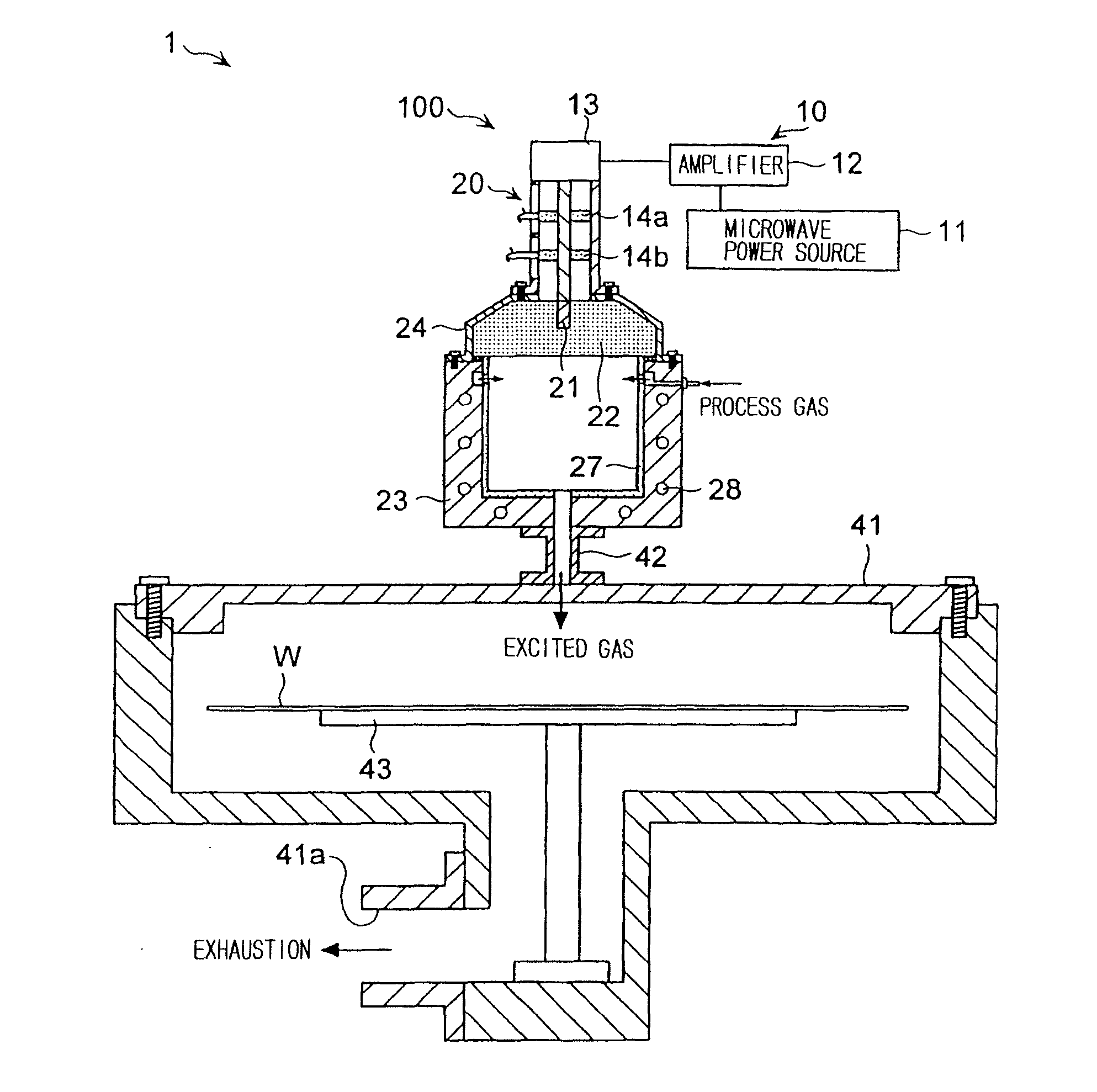
[0008]The present invention is made in view of the above circumstances, and the object thereof is to provide a plasma generating apparatus that has high efficiency of plasma excitation. Another purpose of the present invention is to provide a compact plasma generating apparatus that has good space efficiency. Yet another purpose of the present invention is to provide a remote plasma processing apparatus comprising such plasma generating apparatus.
[0011]Preferable material for the resonator is quartz-type material, single-crystal-alumina-type material, polycrystalline-alumina-type material or aluminum-nitride-type material. It is preferable that a corrosion protection member composed of quartz-type material, single-crystal-alumina-type material or polycrystalline-alumina-type material is applied on the inner surface of the chamber to prevent corrosion of the chamber.
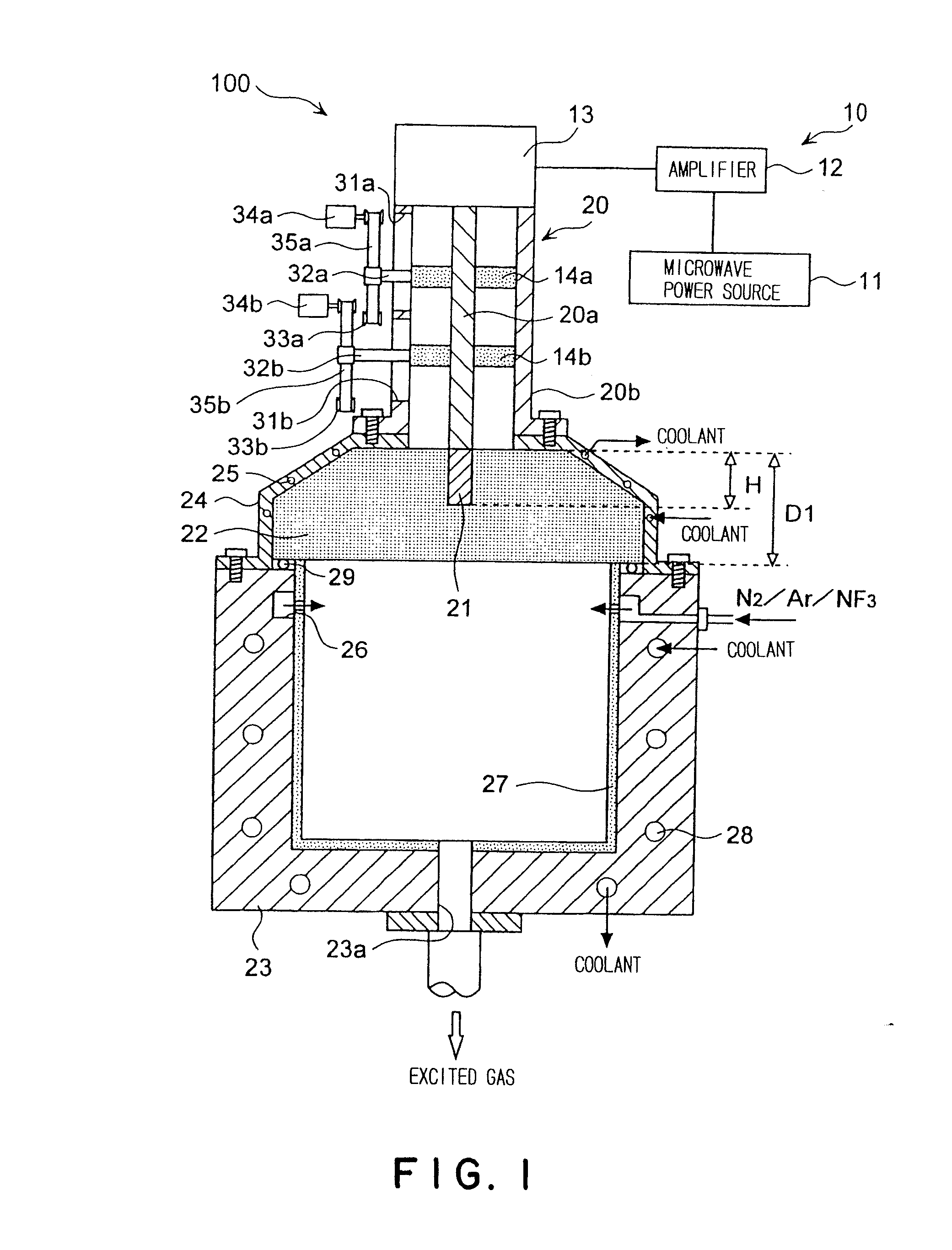
[0012]The chamber preferably has a jacket structure with cooling ability by flowing a coolant in the interior of the members constituting the chamber. In this manner the chamber can be easily cooled down. The chamber also preferably comprises a base-enclosed cylindrical member having said open surface at one end. To efficiently excite a process gas by microwaves, an exhaust vent is formed in the bottom wall of the base-enclosed cylindrical member to discharge the gas excited by microwaves outwardly from the chamber, and a gas discharge opening is formed in the proximity of the open surface side of the side wall of the base-enclosed cylindrical member to discharge the process gas to the interior space.
[0017]The plasma generating apparatus according to the present invention can improve plasma excitation efficiency because the microwave transmission and radiation efficiencies are high and the microwaves radiated from the resonator pass through without any interruption to excite a process gas within the whole interior space of the chamber. In this manner, the whole size of the plasma generating apparatus can be reduced. Such high efficiency also can reduce the amount of a process gas to be used, thereby reducing the running cost. Furthermore, proper configuration settings for the antenna and the resonator can facilitate the generation of standing waves in the resonator, and thus stable plasma can be generated by the microwaves uniformly radiated from the resonator to the chamber.
[0018]In the event that a plurality of antennas are comprised, the advantageous point is that the size of the amplifiers or the like can be reduced wherein small isolators can prevent the damage of the amplifiers caused by the reflected microwaves by using one or some of the antennas for plasma ignition. Furthermore, in the remote plasma processing apparatus according to the present invention, the size reduction of the plasma generating apparatus permits greater latitude in the space utility of the remote plasma processing apparatus, thus reducing the whole size of the remote plasma processing apparatus.

Problems solved by technology

In suchlike remote plasma applicator, however, the part inside the plasma tube used to excite a process gas is limited, and furthermore the coolant tube attached to the gas excitation portion interrupts the microwave transmission into the plasma tube, thus causing a problem that improvement of the plasma excitation efficiency is difficult to achieve.
Although the plasma excitation efficiency can be improved with less winding of the coolant tube around the gas excitation portion, then the gas excitation portion cannot be sufficiently cooled down while the risk of the coolant tube breakage increases.
In addition, suchlike remote plasma applicator has poor space efficiency, thus resulting in a problem of increasing the whole size of the apparatus, due to the structure in which the plasma tube and the waveguide are perpendicular to each other.

Method used


Image

  • Plasma generating apparatus, plasma generating method and remote plasma processing apparatus
  • Plasma generating apparatus, plasma generating method and remote plasma processing apparatus
  • Plasma generating apparatus, plasma generating method and remote plasma processing apparatus

Examples


Embodiment Construction

[0033]The embodiments of the present invention are described below in detail with reference to the drawings. FIG. 1 is a cross-sectional view showing a schematic structure of a plasma generating apparatus 100. The plasma generating apparatus 100 broadly has a microwave generating apparatus 10, a coaxial waveguide 20 comprising an inner tube 20a and an outer tube 20b, a monopole antenna 21 attached to the end of the inner tube 20a, a resonator 22 and a chamber 23.

[0034]The microwave generating apparatus 10 has a microwave power source 11 such as magnetron which generates microwaves of 2.45 GHz frequency for example, an amplifier 12 which regulates the microwaves generated by the microwave power source 11 to a predetermined output level, an isolator 13 which absorbs the reflected microwaves which are output from the amplifier 12 and returning to the amplifier 12, and slug tuners 14a and 14b which are attached to the coaxial waveguide 20. One end of the coaxial waveguide 20 is attached...


PUM

PropertyMeasurementUnit
frequencyaaaaaaaaaa
relative dielectric constantaaaaaaaaaa
dielectric constantaaaaaaaaaa

Abstract

A compact plasma generating apparatus providing high efficiency of plasma excitation is presented. A plasma generating apparatus (100) comprises a microwave generating apparatus (10) for generating microwaves, a coaxial waveguide (20) having a coaxial structure comprising an inner tube (20a) and an outer tube (20b), a monopole antenna (21) being attached to one end of said inner tube (20a), for directing the microwaves generated by said microwave generating apparatus (10) to the monopole antenna (21), a resonator (22) composed of dielectric material for holding the monopole antenna (21), and a chamber (23) in which a specific process gas is fed for plasma excitation. The chamber (23) has an open surface and the resonator (22) is placed on this open surface, and the process gas is excited by the microwaves radiated from the monopole antenna (21) through the resonator (22) into the interior of the chamber (23) to generate plasma.

Description

BACKGROUND OF THE INVENTION[0001]1. Field of the Invention[0002]The present invention relates to a plasma generating apparatus which excites a specific process gas by microwaves, a plasma generating method, and a remote plasma processing apparatus which processes an object to be processed by the excited process gas.[0003]2. Background Art[0004]In the manufacturing process of semiconductor devices or liquid crystal displays, a plasma processing apparatus, such as a plasma etching apparatus and plasma CVD apparatus, is used for plasma processing, such as etching and film formation, on a substrate to be processed, such as a semiconductor wafer and glass substrate.[0005]A known plasma generating method using a remote plasma processing apparatus is realized by a remote plasma applicator having: a plasma tube made of dielectric material through which a process gas is flown; a waveguide aligned perpendicular to this plasma tube; and a coolant tube wound spirally around a portion of the pla...

Claims


Application Information

Patent Timeline
Patent Type & Authority Applications(United States)
IPC IPC(8): C23F1/08C23C16/00C23C16/511
CPCH01J37/3222H01J37/32192
Inventor KASAI, SHIGERU
Owner TOKYO ELECTRON LTD
Learn More