
Device for the Purification of Diesel Exhaust Gases

a technology for purifying devices and exhaust gases, which is applied in the direction of machines/engines, metal/metal-oxide/metal-hydroxide catalysts, arsenic compounds, etc., can solve the problems of increasing the back pressure of exhaust gases to unacceptable values and not adhering to legal limits, so as to reduce the emissions of diesel exhaust gases

Active Publication Date: 2010-09-02
UMICORE AG & CO KG
View PDF5 Cites 27 Cited by
  • Summary
  • Abstract
  • Description
  • Claims
  • Application Information

AI Technical Summary

Benefits of technology

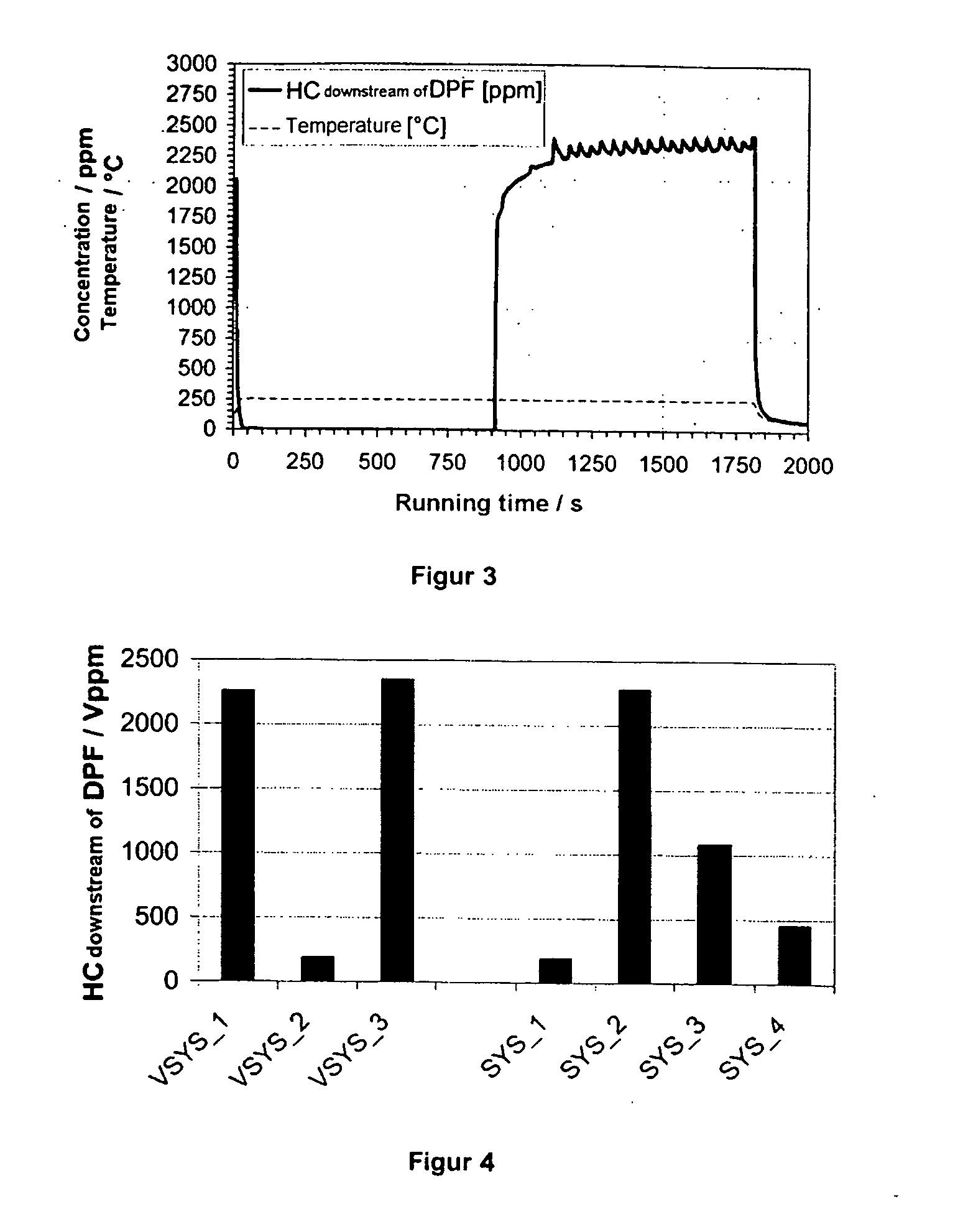
[0015]It is a further important object of the present invention to provide an exhaust-gas purification system having the basic design described in EP-B-1 054 722, in which the oxidation catalyst exhibits the best possible “heat-up performance” in the case of an “active” particle filter regeneration.
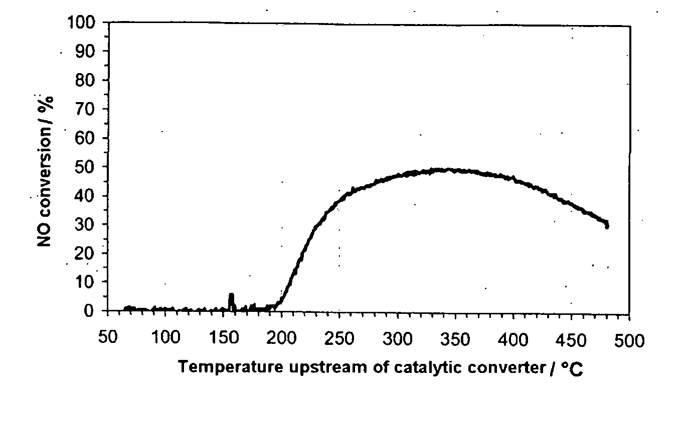
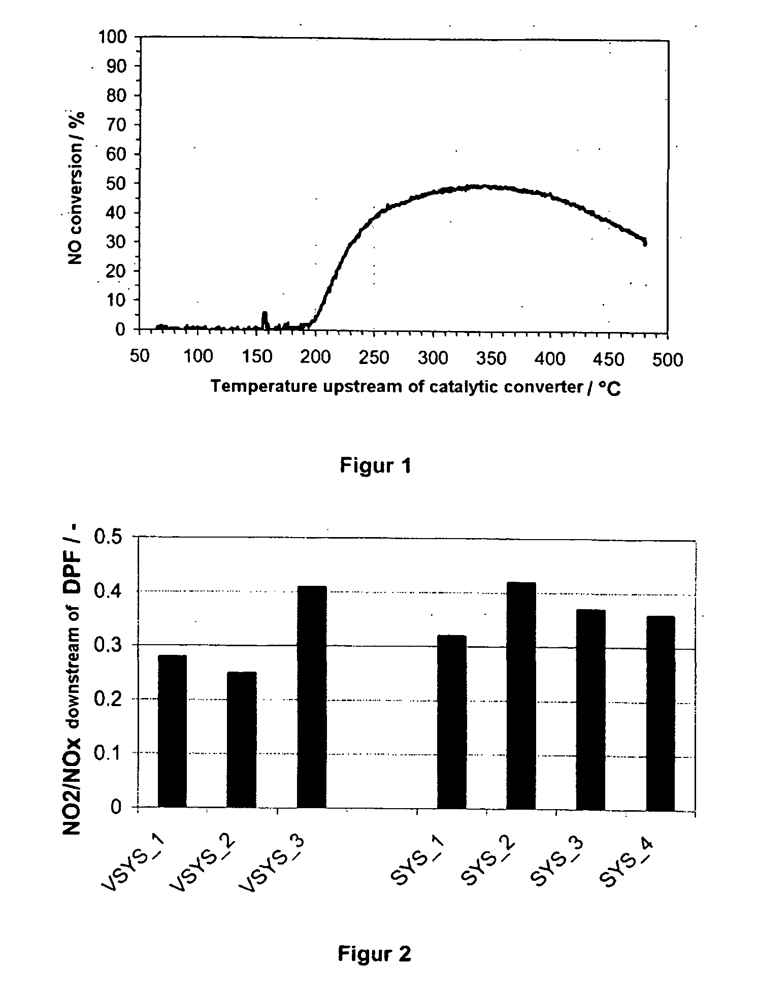
[0020]The inventors have now established that it is advantageous if the significant contribution to the formation of NO2 takes place as the exhaust-gas flow is conducted across the diesel particle filter. This is surprising in that it has hitherto been assumed that a sufficient degree of “passive” filter regeneration can be obtained only by means of high rates of NO2 formation across the oxidation catalytic converter in order to keep the number of supplementary “active” diesel particle filter regenerations as low as possible. The work of the inventors however suggests that an excess expenditure in “active” particle filter regenerations can be avoided with targeted distribution of the noble metals platinum and palladium over the oxidation catalyst and particle filter, and a good “heat-up performance” of the oxidation catalyst can be ensured while simultaneously setting an optimized NO2 / NOx ratio in the exhaust gas upstream of the SCR catalyst.
[0022]In contrast, it has been found that the “heat-up performance” of the oxidation catalyst is improved with increasing noble metal content of the oxidation catalyst, assuming that the ratio of platinum:palladium in the oxidation catalyst does not exceed a value of 6:1. The ratio of platinum:palladium in the oxidation catalyst is preferably between 0.5:1 and 3:1, particularly preferably between 1:1 and 2.5:1. In order to simultaneously obtain an NO2 / NOx ratio downstream of the diesel particle filter which is as optimum as possible for the downstream SCR catalyst, it is necessary for the ratio of platinum:palladium in the catalytically active coating of the diesel particle filter to be no lower than 10:1. The ratio of platinum to palladium in the catalytically active coating of the diesel particle filter is between 12:1 and 14:1 in preferred embodiments.
[0035]The device is suitable for the purification of diesel exhaust gases and may preferably be used in motor vehicles. As the diesel exhaust gases are conducted through the device according to the invention under the conditions typical for this application, all the emissions contained in the diesel exhaust gas are reduced.

Problems solved by technology

A further problem which is not discussed in EP-B-1 054 722 but which occurs in practice is that the “passive” particle filter regeneration which takes place in said system, that is to say the burning of soot, which takes place in situ, by oxidation with NO2 generated by means of the oxidation catalyst, is generally not sufficient on its own to prevent the particle filter from becoming clogged with soot, and a resulting rise in the exhaust-gas back pressure to unacceptable values.
Here, the conversion of the unburned hydrocarbons must be as complete as possible, since the breakthrough of unburned hydrocarbons through the oxidation catalyst can, at the latest at the SCR catalyst which is arranged further downstream, lead to the latter being contaminated.
A breakthrough of unburned hydrocarbons at the end of the exhaust system may also have the result that the legal limits are not adhered to.

Method used


Image

  • Device for the Purification of Diesel Exhaust Gases
  • Device for the Purification of Diesel Exhaust Gases
  • Device for the Purification of Diesel Exhaust Gases

Examples


Embodiment Construction

[0042]Tests in the model exhaust gas:

[0043]For tests in the model exhaust gas, various oxidation catalysts and diesel particle filters were produced. Noble metal quantities and ratios were selected so as to result in the same noble metal costs for all the devices comprising an oxidation catalyst and diesel particle filter.

[0044]To produce oxidation catalysts according to the invention and comparative catalysts, homogeneous silicon-aluminium mixed oxide (5% by weight SiO2 in relation to the overall mass of the mixed oxide; BET surface area: 150 m2 / g) was moistened with an aqueous solution of tetraamineplatinum acetate and tetraaminepalladium nitrate such that the pores of said homogeneous silicon-aluminium mixed oxide were filled, with the powder remaining free-flowing. Here, the noble metal content of the solution and the noble metal ratio were selected corresponding to the target quantities and ratio (cf. table below) to be obtained in the catalysts to be produced. To fix the noble...


PUM


Abstract

The invention relates to a special device for the purification of diesel exhaust gases, which device comprises, in the flow direction of the exhaust gas, an oxidation catalyst, a diesel particle filter with catalytically active coating, and, downstream of a device for introducing a reducing agent from an external reducing agent source, an SCR catalyst. The oxidation catalyst and the catalytically active coating of the diesel particle filter contain palladium and platinum. The ratio of the noble metals platinum and palladium in the overall system and on the individual components, oxidation catalyst and catalytically coated diesel particle filter, are coordinated with one another in such a way as to obtain firstly an optimum NO / NO2 ratio in the exhaust gas upstream of the downstream SCR catalyst, and secondly optimum heating and HC conversion behaviour during an active particle filter regeneration.

Description

INTRODUCTION AND BACKGROUND[0001]The invention relates to a special device for the purification of diesel exhaust gases, which device comprises, in the flow direction of the exhaust gas, an oxidation catalyst, a diesel particle filter with catalytically active coating, and, downstream of a device for introducing a reducing agent from an external reducing agent source, an SCR catalyst.[0002]The untreated exhaust gas of diesel engines contains, in addition to carbon monoxide CO, hydrocarbons HC and nitrogen oxides NOx, a relatively high oxygen content of up to 15% by volume. Said untreated exhaust gas also contains particle emissions which are composed predominantly of soot residues and possible organic agglomerates and which arise from partially incomplete fuel combustion in the cylinder.[0003]Adhering to future legal exhaust-gas limits for diesel vehicles in Europe, North America and Japan, necessitates the simultaneous removal of particles and nitrogen oxides from the exhaust gas. ...

Claims


Application Information

Patent Timeline
IPC IPC(8): B01D53/94F01N3/035B01D50/00
CPCB01D53/9418B01D53/944B01D53/9477B01D2251/206B01D2255/1021F01N13/009B01D2258/012F01N3/2066F01N2570/14Y02T10/24B01D2255/1023F01N3/035B01J23/44Y02T10/12F01N3/20B01D53/94F01N3/023
Inventor SCHNEIDER, WOLFGANGMUSSMANN, LOTHARJESKE, GERALDSCHIFFER, MICHAELPFEIFER, MARCUS
Owner UMICORE AG & CO KG
Learn More