Three-dimensionally bending machine, bending-equipment line, and bent product

a three-dimensional bending machine and equipment technology, applied in the direction of manufacturing tools, transportation and packaging, heating/cooling devices, etc., can solve the problems of difficult to prevent the occurrence of uneven distortion, the accuracy of bending operation cannot be guaranteed, and the cooling speed cannot be accurately controlled. , to achieve the effect of preventing ensuring the accuracy of bending operation, and reducing the generation of seizure defects

Active Publication Date: 2010-09-02
NIPPON STEEL CORP
View PDF36 Cites 13 Cited by
  • Summary
  • Abstract
  • Description
  • Claims
  • Application Information

AI Technical Summary

Benefits of technology

[0039]According to the three-dimensionally bending machine, and the three-dimensional-bending-equipment line in accordance with the above-described aspects of the present invention, even when a workpiece is bent in various shapes, such as in a two-dimensional continuous bending operation in which the workpiece is two-dimensionally bent in different directions (for example, an S shape) or in a three-dimensional continuous bending operation in which the workpiece is three-dimensionally bent in different directions, and even when a workpiece having high strength is bent, the workpiece is uniformly cooled down, whereby it is possible to effectively obtain a metal product having excellent shape fixability despite having high strength, and uniform hardness distribution at a low cost.
[0040]Further, since the three-dimensionally movable unit rotatably clamps a workpiece, it is possible to retard the generation of seizure defects on the surface of roller-dies in the three-dimensionally movable unit. Therefore, the accuracy of a bending operation can be ensured, and a bending operation can be performed with a high degree of operation efficiency.

Problems solved by technology

However, in the grab bending method disclosed in Japanese Patent Application Publication No. 50-59263 and Japanese Patent No. 2816000, since the feeding speed of the metal tube varies significantly, the cooling speed cannot be accurately controlled, and a high degree of quenching accuracy cannot be ensured, which makes it difficult to prevent the occurrence of uneven distortion.
Thus, products made by the grab bending method are not suitable for parts of an automobile.
Further, the bending machine disclosed in Japanese Patent No. 3195083 is based on push-through bending, but is not directed to obtain a metal material having high strength by performing hot working on a metal tube having low strength as a starting material and then performing quenching on the heated metal tube to increase the strength of the metal tube.
In addition, the surface of the movable gyro die is susceptible to seizure defects on due to the heating of the metal tube.

Method used


Image

  • Three-dimensionally bending machine, bending-equipment line, and bent product
  • Three-dimensionally bending machine, bending-equipment line, and bent product
  • Three-dimensionally bending machine, bending-equipment line, and bent product

Examples


Embodiment Construction

[0055]Hereinafter, the overall configuration of a three-dimensionally bending machine, an example structure of a supporting unit, the structure of a feeding unit, an example structure of a heating and cooling unit, the structure of a three-dimensionally movable unit, the feature and operation of a preheating unit, the structure and layout of an articulated robot, and the characteristics of a three-dimensional-bending-equipment line according to exemplary embodiments of the present invention will be described with reference to the accompanying drawings.

[0056]1. Overall Structure of Three-Dimensionally Bending Machine and Example of Structure of Supporting Unit

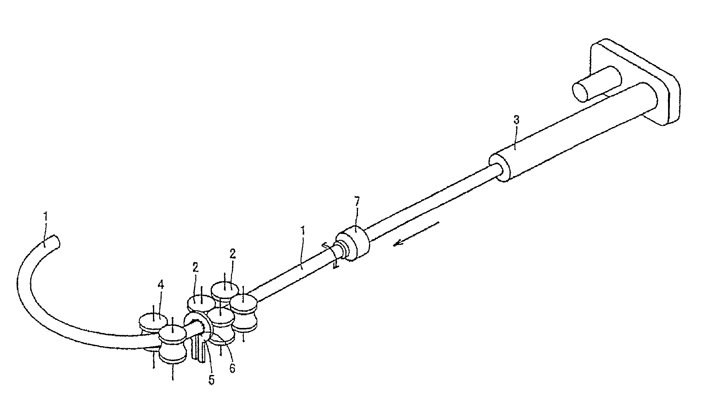
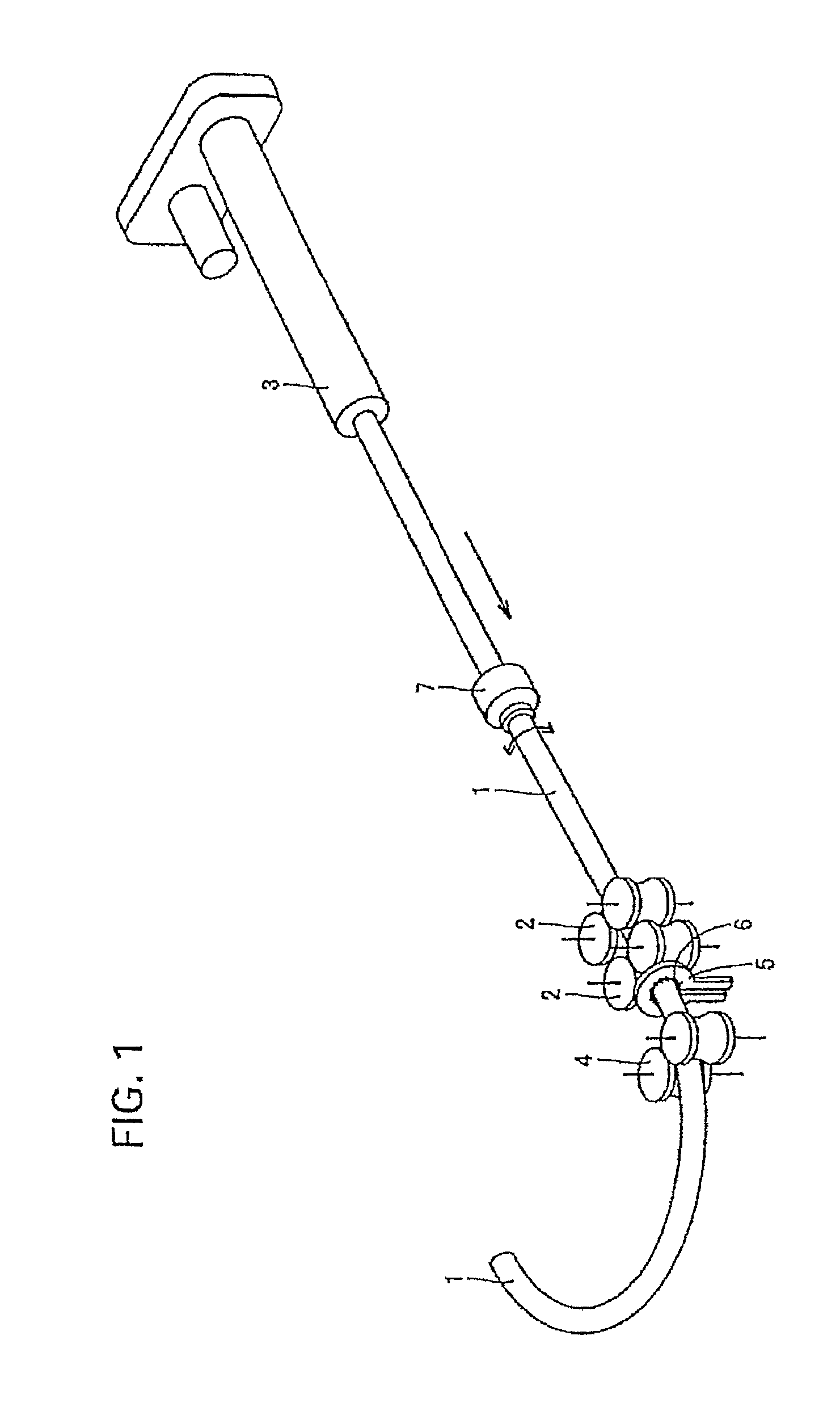
[0057]FIG. 1 is a diagram illustrating the overall structure of a three-dimensionally bending machine for performing a bending operation according to the present invention. In the bending method, a workpiece 1 as a starting material that is rotatably supported by a supporting unit 2, is successively or continuously fed from an u...


PUM

PropertyMeasurementUnit
tensile strengthaaaaaaaaaa

Abstract

A three-dimensionally bending machine comprises a supporting unit to support a workpiece and a feeding unit to feed the workpiece from an upstream side of the workpiece. A heating and cooling unit, provided around the outer circumference of a portion of the workpiece downstream of said supporting unit heats the portion of workpiece in a temperature range for plastic deformation and quenches and rapidly cools the deformed workpiece. A three-dimensionally movable unit, provided downstream of said heating and cooling unit, supports the metal material and controls the supporting position and/or the moving speed of the metal material to apply the bending moment in association with a feed amount, a heating amount, and a cooling amount of the workpiece. Even when a high-strength workpiece is bent, a workpiece having excellent shape fixability and uniform hardness distribution can be made, especially for application to sophisticated automobile parts.

Description

[0001]This is a continuation-in-part of U.S. application Ser. No. 11 / 896,319 filed Aug. 31, 2007, which is a continuation of PCT / JP2006 / 303220 filed Feb. 23, 2006. The PCT application was not in English as published under PCT Article 21(2).TECHNICAL FIELD[0002]The present invention relates to a bending machine, a bending-equipment line, and more particularly, to a three-dimensionally bending machine and a three-dimensionally bending-equipment line, and to a bent product made by the three-dimensionally bending machine or the three-dimensionally bending-equipment line.BACKGROUND ART[0003]In recent years, demands for structural metal materials having high strength and light weight have increased in consideration of global environment. For example, in an automobile industry, there are growing demands for the safety of car body, and high-strength and light-weight parts of an automobile are increasingly required, so that parts of an automobile have been developed in order to improve fuel ...

Claims


Application Information

Patent Timeline
Patent Type & Authority Applications(United States)
IPC IPC(8): B21D7/16
CPCB21D7/08B21D7/16B21D7/165B21D7/162Y10T428/1241
Inventor TOMIZAWA, ATSUSHIKIKUCHI, FUMIHIKOKUWAYAMA, SHINJIRO
Owner NIPPON STEEL CORP
Why Eureka
Try Eureka