
Closure Assembly for Electrochemical Cells

a technology of electrochemical cells and assembly parts, applied in the direction of cell components, vent arrangements, batteries, etc., can solve the problems of adversely affecting the activation of the ptc, improper installation of cells, and excess heat generated by the ptc device, so as to maintain reliable, compressive sealing forces, and reduce the surface area or shape of the ptc device.

Inactive Publication Date: 2010-08-26
ENERGIZER BRANDS
View PDF25 Cites 42 Cited by
  • Summary
  • Abstract
  • Description
  • Claims
  • Application Information

AI Technical Summary

Benefits of technology

[0014]In view of the above, the invention contemplates, inter alia, a lithium electrochemical cell design with a PTC device that has the ability to limit current flow therethrough at desired temperatures (typically occurring under abusive conditions), while at the same time not limiting the ability of the PTC device to activate and without substantially reducing its surface area or shape. Additionally, this cell design maintains reliable, compressive sealing forces over extended periods of time both before and after activation of the PTC device and without directly exposing the PTC device to the organic solvents of the electrolyte.
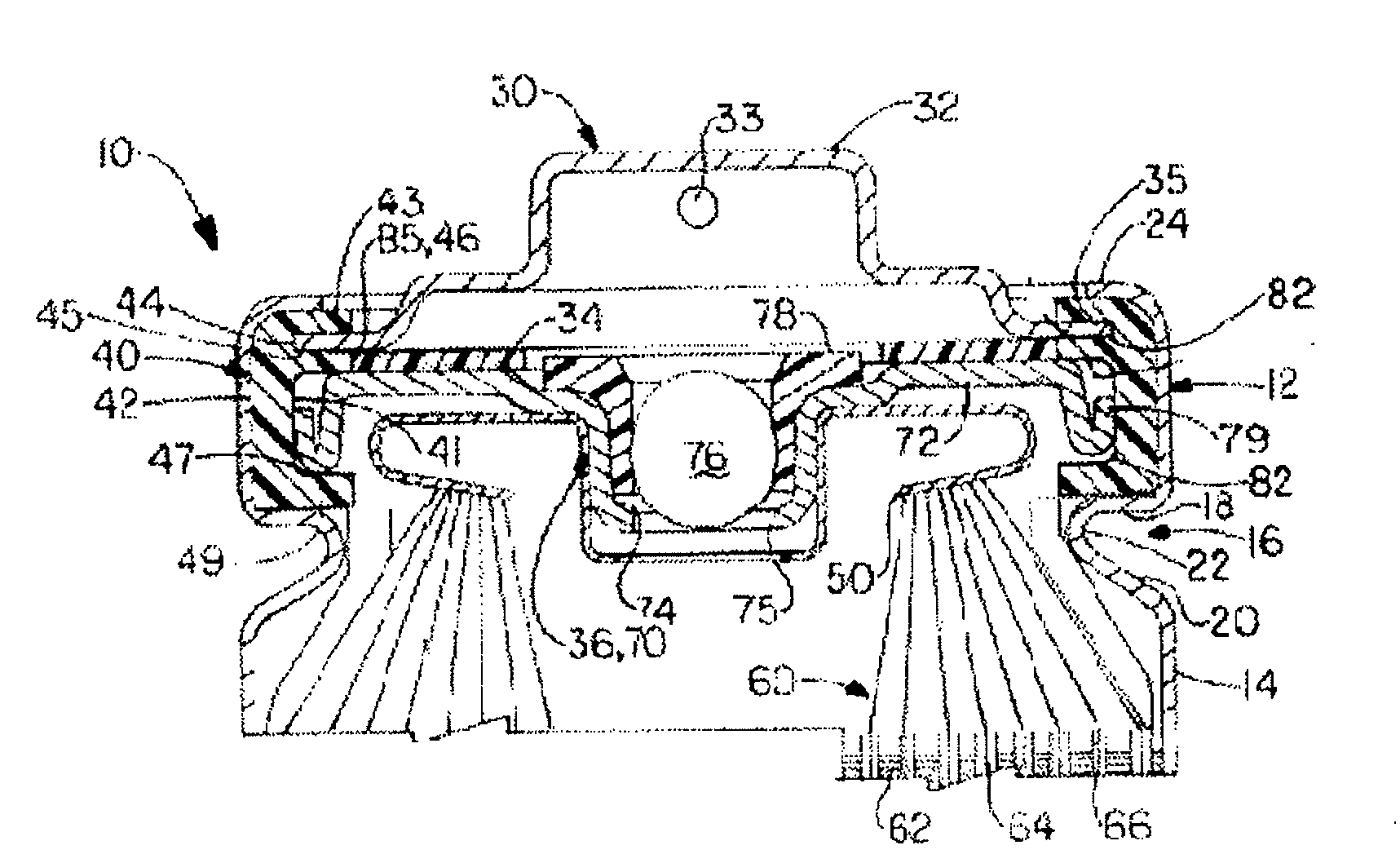
[0017]By altering the cross sectional shape of the sealing gasket, the PTC device is removed from the compressive forces necessary to effectively seal the battery, both during manufacturing and the subsequent storage / use of the battery. This arrangement allows the PTC device to: i) avoid damage during manufacture, ii) expand during activation and iii) reduce electrical resistance by maximizing the surface area for electrical connection between the internal electrode of the battery and the external terminal of the battery housing.
[0019]In one embodiment, the annular seal member (i.e., the sealing gasket) has an E-shape cross section (in a final, closed cell), although the original cross sectional shape of the gasket may be similar to an F-shape where crimping of the open end partially or completely compresses a terminal flange of the gasket in a radial direction. In each instance, a radial protrusion oriented along the the axial inner side wall of the annular gasket is constructed to fit concentrically around the PTC device. The gasket may also have upper and lower flanges which protrude radially inward at the upper and lower terminus of the inner diameter of the annulus. The protrusion has a greater height (measured along the axis of the container) as compared to the PTC device. Because the protrusion, and more generally the entire gasket, is constructed from a material that maintains its rigidity at the activation temperature of the PTC device, the protrusion helps to shield the PTC device from unwanted primary axial compression forces, both during manufacture of the cell and in the subsequent operation thereof. The protrusion also permits other features of the end assembly, which is associated with the PTC device, to be received by the gasket, thereby imparting a better radial and axial seal between the assembly, the gasket and the container. Multiple protrusions may also be provided. Additionally or alternatively, the upper and lower flanges need not be specifically molded to have inward protrusions and instead could be shaped by the closing process of the cell itself (e.g., crimping).

Problems solved by technology

For example, excess heat sufficient to activate the PTC device may be generated in an electrochemical cell as a result of external short circuit, attempting to recharge a primary cell, improperly charging a rechargeable cell, forced overdischarge, or improper installation of cells in a device.
Insofar as the PTC device is often connected to the cover, this closure may subject the PTC device to compressive axial forces that adversely affect the activation of the PTC.
Gasket materials that softens at a temperature below the activation of the PTC device have also been used, but this may eliminate the use of the best performing materials.
Yet another approach is to locate the PTC outside of the container, but this requires a means for attaching the PTC to the can / cover and increases the likelihood of damage to the PTC.
In some embodiments of this latter patent, a PTC device is located between a bead and a crimped portion of the open end of the container, adjacent one or more of a terminal cover; however, this arrangement subjects the PTC device to compressive axial forces during sealing of the cell.
In both instances, these arrangements necessarily require welding or adhesively fixing the PTC resistor to an additional conductive sealing member and the PTC resistor must have a diameter that is substantially smaller than the inner diameter of the battery can, thereby limiting the amount of surface area and overall effectiveness of the PCT resistor.
Notably, this device requires numerous moving parts and relies solely on the internal pressure within the cell caused by overheating the electrolyte, rather than being activated by the electrical demands (i.e., the load) placed on the cell.
The inclusion of additional parts (e.g., two or more gaskets) increases manufacturing complexity and cost.
Here, the PTC device avoids exposure to crimping forces by limiting its overall diameter, although this limited diameter reduces the effectiveness of the PTC device by limiting the amount of surface area in contact with the electrode.
Moreover, this central location of the PTC device prevents the inclusion of common venting devices.
In such instances, the PTC device must not react with or dissolve in the organic solvents, thereby presenting a significant technical challenge in terms of chemical compatibility.

Method used


Image

  • Closure Assembly for Electrochemical Cells
  • Closure Assembly for Electrochemical Cells
  • Closure Assembly for Electrochemical Cells

Examples


Embodiment Construction

[0030]As used throughout this specification, the term “electrochemical cell” is afforded a broad meaning, including any system capable of producing electrical current with a positive electrode, a negative electrode, a separator and an electrolyte, although the invention is most applicable to systems using nonaqueous electrolytes. A cylindrical container is any tubular container, with at least one open end, whose axial height is greater than its diameter. In the context of the gasket, a “protrusion” or “projection” is a horizontally-oriented feature that projects radially inward from the axial sidewall of the gasket; as such, a protrusion is structurally and functionally distinct from a flange oriented at the top or bottom of the gasket (irrespective of whether the flange is crimped or positioned in a radial direction or more of an axial direction).

[0031]The invention relates to electrochemical cells, preferably containing lithium or lithium alloy as an electrochemically active mater...


PUM


Abstract

An end assembly seals a cylindrical electrochemical cell. The assembly includes a positive temperature coefficient (PTC) device and a gasket having a protrusion that cooperates with the end assembly isolates the PTC device from primary axial compression forces present in the closure assembly. In further embodiments of the present invention, the end assembly may be produced by insert molding a seal element about the terminal cover and the gasket itself has an E or F shaped cross section.

Description

FIELD OF THE INVENTION[0001]The present invention relates to a closure assembly for an electrochemical cell. More particularly, a primary lithium-containing electrochemical cell is disclosed. The cell has a closure assembly comprising a cover, a sealing gasket with a shelf disposed along its axial middle portion and a positive temperature coefficient (PTC) device, wherein the arrangement of the closure isolates the PTC from primary axial compression forces. A preformed seal assembly produced by insert molding the gasket around the cover.BACKGROUND OF THE INVENTION[0002]A related patent application, also entitled “Closure Assembly for Electrochemical Cells” and having U.S. Patent application Ser. No. ______, was filed on the same day as this application and is hereby incorporated by reference.[0003]Electrochemical cells, including but not limited to those with a lithium metal or alloy as an electrochemically active material, often utilize one or more positive temperature coefficient ...

Claims


Application Information

Patent Timeline
IPC IPC(8): H01M2/12B31F1/08H01M50/167H01M50/184H01M50/186H01M50/572
CPCH01M2/0413H01M2/08H01M2/12H01M10/5026H01M2/34H01M2200/106H01M2/348H01M2/1241H01M10/637Y02E60/10H01M50/171H01M50/30H01M50/3425H01M50/572H01M50/581H01M50/184H01M50/186H01M50/167H01M50/107
Inventor WENDLING, MATTHEW T.SCHUBERT, MARK A.WU, JAMES X.
Owner ENERGIZER BRANDS
Learn More