
Color ccd linear image sensor

Inactive Publication Date: 2010-08-19
RENESAS ELECTRONICS CORP
View PDF0 Cites 11 Cited by
  • Summary
  • Abstract
  • Description
  • Claims
  • Application Information

AI Technical Summary

Benefits of technology

[0030]According to the present invention, it is possible to improve output sensitivity of the color CCD linear image sensor and to achieve reduction in the sensor size.

Problems solved by technology

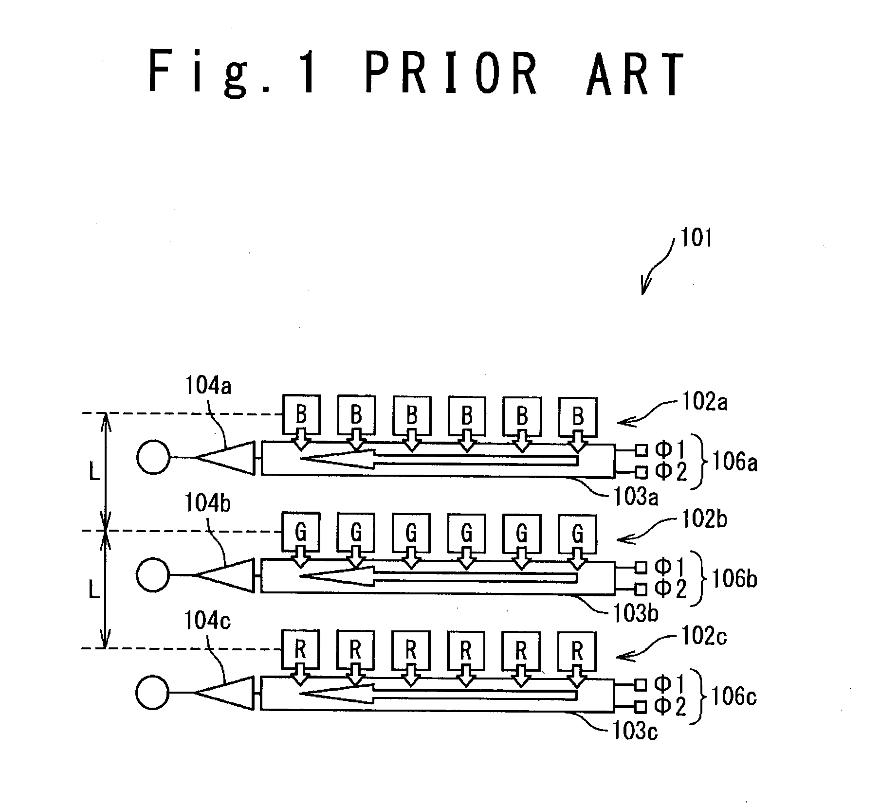
The color CCD linear image sensor 101 illustrated in FIG. 1 has a disadvantage that RGB line intervals L are required in the scanning direction, and therefore a chip size is increased.
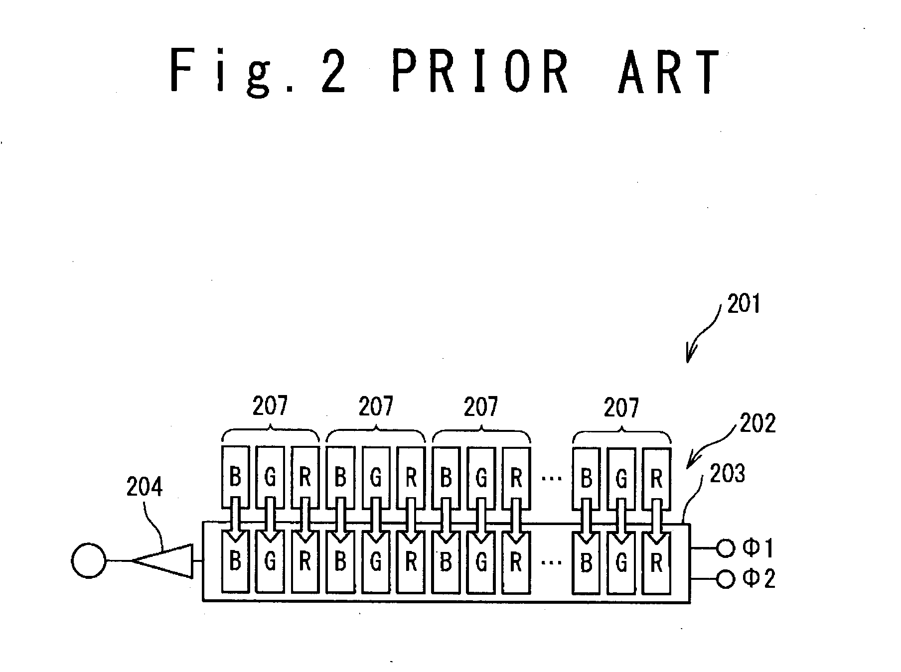
The color CCD linear image sensor 201 does not require the line interval L, and therefore the chip size in the vertical direction may be reduced; however, there is a disadvantage of low sensitivity because the three pixels for RGB constitutes the one unit.
Consequently, in the color CCD linear image sensor 201, it is difficult to decrease a size and achieve both a reduction in manufacturing cost and improvement in output sensitivity without use of the optical low pass filter.
In a color CCD linear image sensor based on the TDI method such as the color CCD linear image sensor 321 illustrated in FIG. 4, each of the RGB light receiving parts (the first light receiving part 322a, the second light receiving part 322b, and the third light receiving part 322c) has a plurality of stages of pixels in the scanning direction, which requires regions for the RGB line intervals L, and therefore there is a disadvantage of an increase in a chip size.
Further, as the number of pixels is increased in the scanning direction to improve sensitivity, the RGB line interval is increased, and therefore it is difficult to decrease the size.
For this reason, an area should be increased in both of the horizontal and scanning directions, which makes it difficult to decrease a device size.
Consequently, there arises a problem of reduction in yield in a manufacturing process.

Method used


Image

  • Color ccd linear image sensor
  • Color ccd linear image sensor
  • Color ccd linear image sensor

Examples


first embodiment

[0048]An embodiment of the present invention is described below on the basis of the drawings. Note that in the diagrams for describing the embodiment, the same member is denoted by the same reference numeral in principle, and redundant description thereof is omitted.

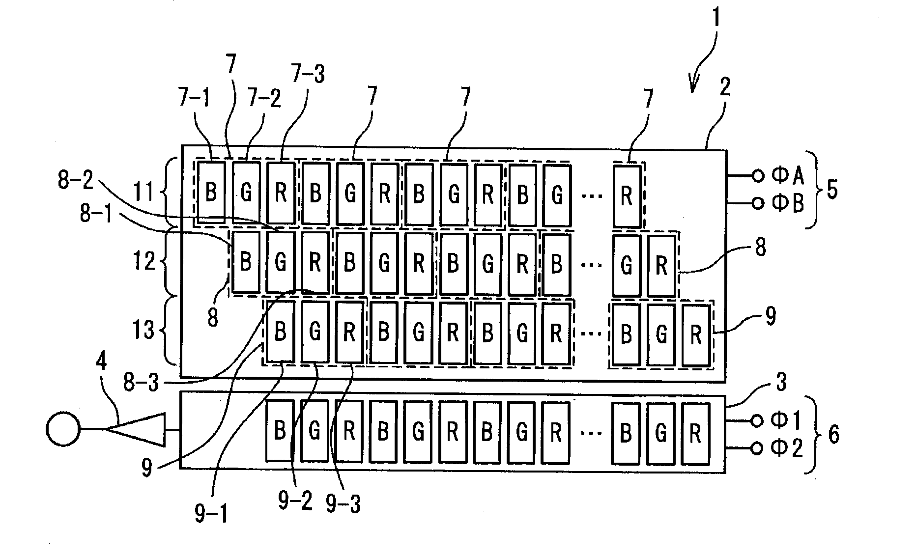
[0049]FIG. 6 is a plan view exemplifying a configuration of a color CCD linear image sensor 1 according to a first embodiment. The color CCD linear image sensor 1 includes a light receiving part 2, a charge transfer part 3 and an output part 4. The light receiving part 2 is connected to drive clock supply terminals 5 that supply a light receiving part first clock φA and a light receiving part second clock φB. The charge transfer part 3 is connected to transfer clock supply terminals 6 that supply a CCD first clock φ1 and a CCD second clock φ2.

[0050]The light receiving part 2 includes a first pixel column 11, a second pixel column 12 and a third pixel column 13. In the first pixel column 11, a plurality of first-column ba...

second embodiment

[0063]FIG. 11 is a plan view exemplifying a configuration of the color CCD linear image sensor 1 according to a second embodiment of the present invention. In the color CCD linear image sensor 1 of the second embodiment, the light receiving part 2 includes a light receiving part first region 2a and a light receiving part second region 2b. The light receiving part first region 2a corresponds to the first pixel column 11, the second pixel column 12 and the third pixel column 13. The light receiving part second region 2b corresponds to a fourth pixel column 21, a fifth pixel column 22 and a sixth pixel column 23. The color CCD linear image sensor 1 of the second embodiment has the effective aperture 17 similar to that of the color CCD linear image sensor 1 in the first embodiment, and the number of TDI stages of the light receiving part 2 in the horizontal direction is increased. Due to this configuration of the color CCD linear image sensor 1, further improvement in the sensitivity is...


PUM


Abstract

A color CCD linear image sensor has: first basic pixels arranged in a first column and configured to accumulate first-column pixel charges; and second basic pixels arranged in a second column adjacent to the first column and configured to add accumulated charges to the first-column pixel charges to generate second-column pixel charges. The first basic pixels include a first-column first-color pixel, a first-column second-color pixel adjacent to the first-column first-color pixel, and a first-column third-color pixel adjacent to the first-column second-color pixel. The second basic pixels include a second-column first-color pixel, a second-column second-color pixel adjacent to the second-column first-color pixel, and a second-column third-color pixel adjacent to the second-column second-color pixel. The second-column first-color pixel is arranged adjacent to the first-column second-color pixel.

Description

INCORPORATION BY REFERENCE[0001]This application is based upon and claims the benefit of priority from Japanese patent application No. 2009-035573, filed on Feb. 18, 2009, the disclosure of which is incorporated herein in its entirety by reference.BACKGROUND OF THE INVENTION[0002]1. Field of the Invention[0003]The present invention relates to a color CCD linear image sensor.[0004]2. Description of Related Art[0005]In recent years, a scanner as a peripheral device of a personal computer is widely spread, and improvement in performance of a copier is required. Consequently, demand for a color CCD linear image sensor to read a color image is increasing. Such the color CCD linear image sensor includes: a light receiving part that is provided with a photodiode; a gate part that uses a read pulse to read signal charges generated in the light receiving part; a signal charge transfer part; and an output part that is connected to an external signal processing circuit. The signal charge trans...

Claims


Application Information

Patent Timeline
IPC IPC(8): H04N5/335H01L27/148H01L31/10H04N1/028
CPCH04N9/045H04N5/37206H04N25/711H04N23/84H04N25/134
Inventor IIJIMA, TAKASHI
Owner RENESAS ELECTRONICS CORP
Learn More