
Method and apparatus for controlling diameter of a silicon crystal ingot in a growth process

a growth process and silicon crystal technology, applied in the direction of crystal growth process, chemistry apparatus and processes, polycrystalline material growth, etc., can solve the problems of inability to accurately understand the diameter of the ingot and the response to a change in pull-speed, and the oversimplification of the relationship between the diameter and the pull-speed problem

Active Publication Date: 2010-08-19
SUMCO PHOENIX CORP
View PDF12 Cites 6 Cited by
  • Summary
  • Abstract
  • Description
  • Claims
  • Application Information

AI Technical Summary

Benefits of technology

The present invention provides a method for growing silicon ingots with a uniform diameter along their lengths. The method uses a feedback control system based on a linear relationship between the meniscus taper and the pull-speed of the ingot. This allows for accurate control of the diameter of the ingot. The method is simple and well-suited for industrial application. Additionally, the invention addresses the issue of pull-speed variations and provides a new method for controlling the diameter of the ingot by integrating the taper error.

Problems solved by technology

The PID controller can also be used in controlling systems which are governed by a non-linear equation or a linear differential equation of more than order 2, however, at the cost of control performance and stability.
Unfortunately, it is not correctly understood exactly how the ingot diameter responds to a change of the pull-speed.
However, this is rather an oversimplification of the relationship between the diameter and the pull-speed.
Thus, although it is true that a change of the pull-speed causes a change of the diameter, it is a misunderstanding to think that the diameter can be controlled directly by changing the pull-speed.

Method used


Image

  • Method and apparatus for controlling diameter of a silicon crystal ingot in a growth process
  • Method and apparatus for controlling diameter of a silicon crystal ingot in a growth process
  • Method and apparatus for controlling diameter of a silicon crystal ingot in a growth process

Examples


Embodiment Construction

[0036]Hereinafter, a detailed explanation of the method and apparatus for controlling the diameter of a monocrystalline silicon ingot according to the present invention will be given with reference to the attached drawings.

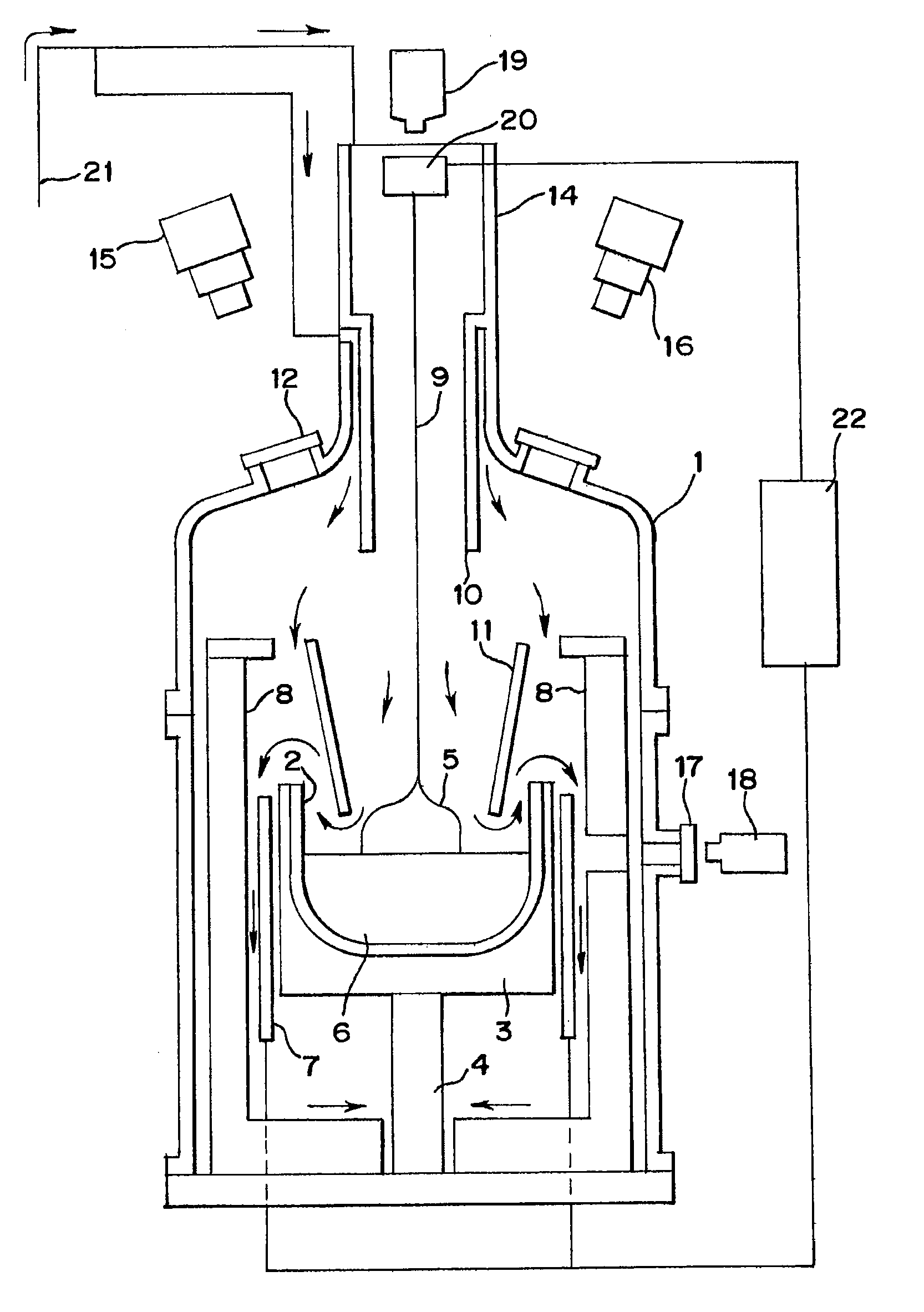
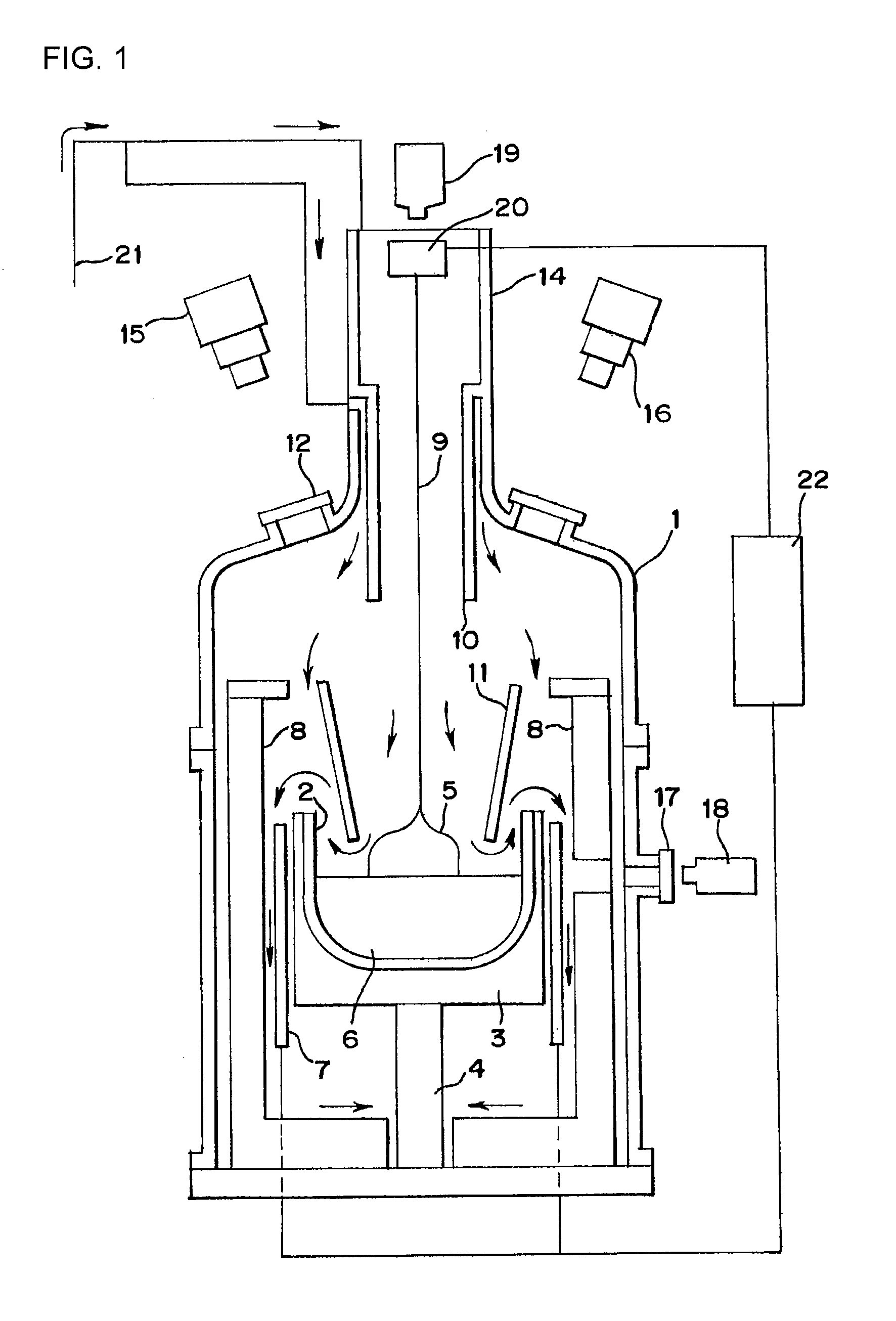
[0037]Referring now to FIG. 1, an apparatus according to the present invention is shown for use in implementing a CZ crystal growing process. In this figure, the apparatus comprises a furnace 1. Inside the furnace 1, a quartz crucible 2 is provided which holds silicon melt 6. The quartz crucible 2 is received by a graphite susceptor 3, which is fixed at the top of a drive shaft 4. The drive shaft 4 moves vertically and rotates to thereby move the quartz crucible 2 vertically and also rotate it. A carbon heater 7 surrounds the susceptor 3 and heats the crucible 2 to control the temperature of the silicon melt 6 in the crucible 2. An insulation tube 8 is placed between the heater 7 and the furnace wall.

[0038]A tubular radiation heat shield 11 is suspended above the ...


PUM

PropertyMeasurementUnit
speedaaaaaaaaaa
pull-speedaaaaaaaaaa
diameter error detectoraaaaaaaaaa

Abstract

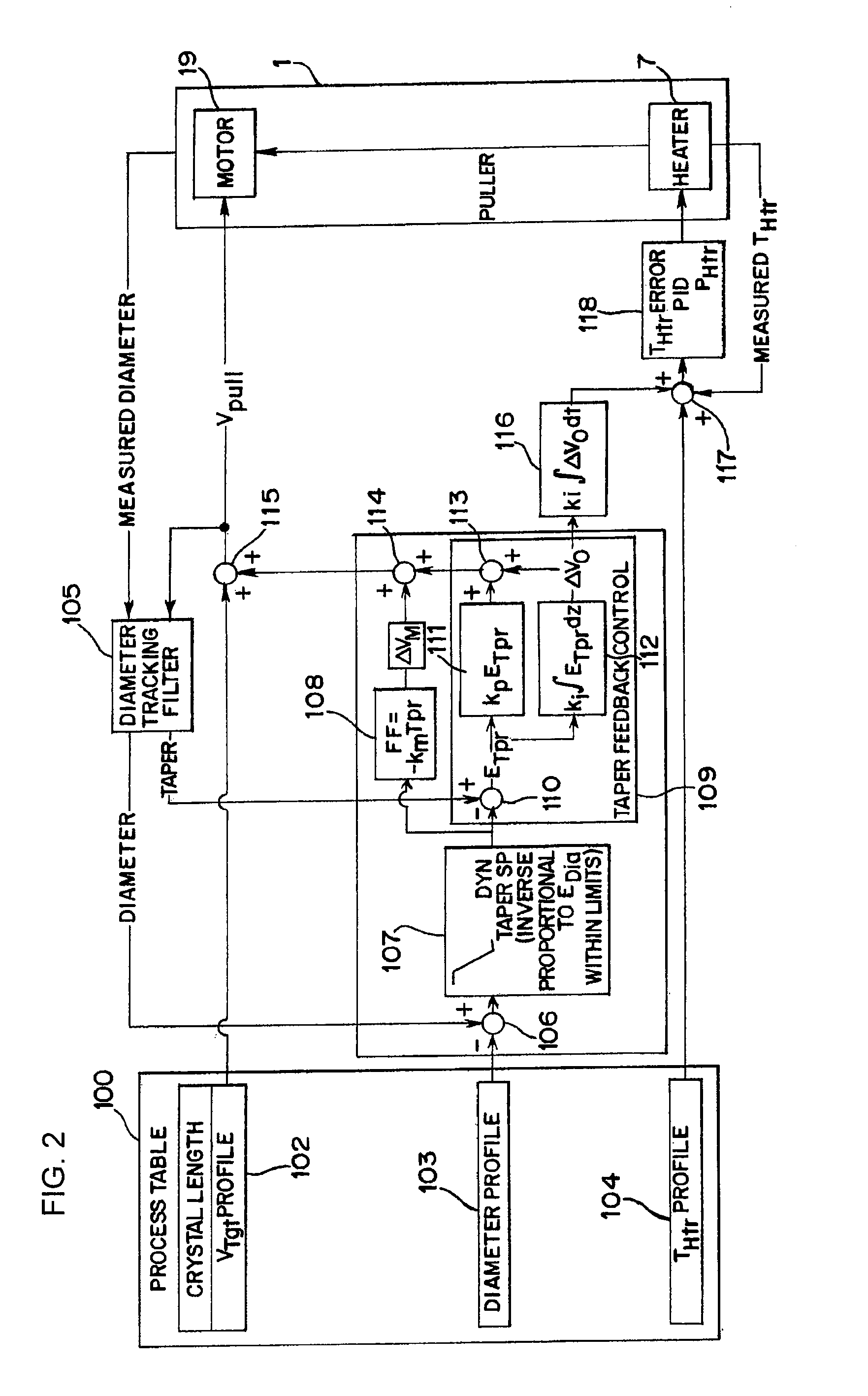
An improvement to a method and an apparatus for growing a monocrystalline silicon ingot from silicon melt according to the CZ process. The improvement performs defining an error between a target taper of a meniscus and a measured taper, and translating the taper error into a feedback adjustment to a pull-speed of the silicon ingot. The conventional control model for controlling the CZ process relies on linear control (PID) controlling a non-linear system of quadratic relationship defined in the time domain between the diameter and the pull-speed. The present invention transforms the quadratic relationship in the time domain between the diameter and the pull-speed into a simile, linear relationship in the length domain between a meniscus taper of the ingot and the pull-speed. The present invention applies a linear control (modified PID) which operates in the length domain, and controls a system that has a linear relationship between the ingot taper and the pull-speed in the length domain to control the diameter of a growing silicon ingot.

Description

RELATED APPLICATIONS[0001]This application is a division of U.S. patent application Ser. No. 12 / 184,016 filed on Jul. 31, 2008, the entire content of which is hereby incorporated by reference.BACKGROUND OF THE INVENTION[0002]This invention relates generally to improvements in controlling the growth process of a monocrystalline silicon ingot and, particularly, to a method and apparatus for accurately controlling the diameter of a monocrystalline silicon ingot during its growth process.[0003]The Czochralski (CZ) process is used to obtain monocrystals. The most important application thereof is growing a monocrystalline silicon ingot, which is sliced into silicon wafers for fabrication of semiconductor circuits thereon. Briefly described, the CZ process includes melting a charge of polycrystalline silicon in a quartz crucible and lifting a monocrystalline seed from the surface of the melt silicon. As the seed is being lifted from the melted silicon, monocrystalline silicon grows from th...

Claims


Application Information

Patent Timeline
Patent Type & Authority Applications(United States)
IPC IPC(8): C30B15/24
CPCC30B15/22C30B29/06Y10T117/1024Y10T117/1008Y10T117/10Y10T117/1032Y10T117/1004C30B15/20
Inventor ORSCHEL, BENNOKEARNS, JOELTAKANASHI, KEIICHITODT, VOLKER
Owner SUMCO PHOENIX CORP
Learn More