Eureka AIR delivers breakthrough ideas for toughest innovation challenges, trusted by R&D personnel around the world.

Implantable Sensor

Inactive Publication Date: 2010-08-12
GLUSENSE LTD
View PDF27 Cites 53 Cited by
  • Summary
  • Abstract
  • Description
  • Claims
  • Application Information

AI Technical Summary

Benefits of technology

[0067]In an embodiment, reducing the binding includes facilitating consumption of the analyte by algae.
[0093]In an embodiment, the apparatus includes a line of cells selected from the group consisting of: COS7 cells, and HepG2 cells, and the apparatus is configured to reduce the binding by facilitating consumption of the analyte by the line of cells selected from the group consisting of: COS7 cells, and HepG2 cells.

Problems solved by technology

Fibrotic overgrowth around the implanted cells, however, gradually impairs substance exchange between the cells and their environment.
Hypoxia of the cells typically leads to cell death.
Diabetes is a disorder that affects many people and results from the inability of the body to properly utilize and metabolize carbohydrates, particularly glucose.
Abnormal levels of glucose in the blood cause many complications and pathologies, leading to premature death in many cases.

Method used


Image

  • Implantable Sensor
  • Implantable Sensor
  • Implantable Sensor

Examples


Embodiment Construction

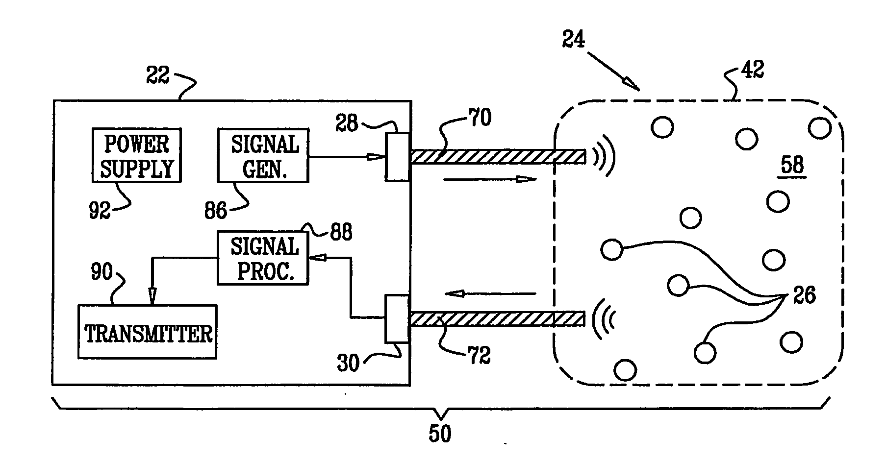
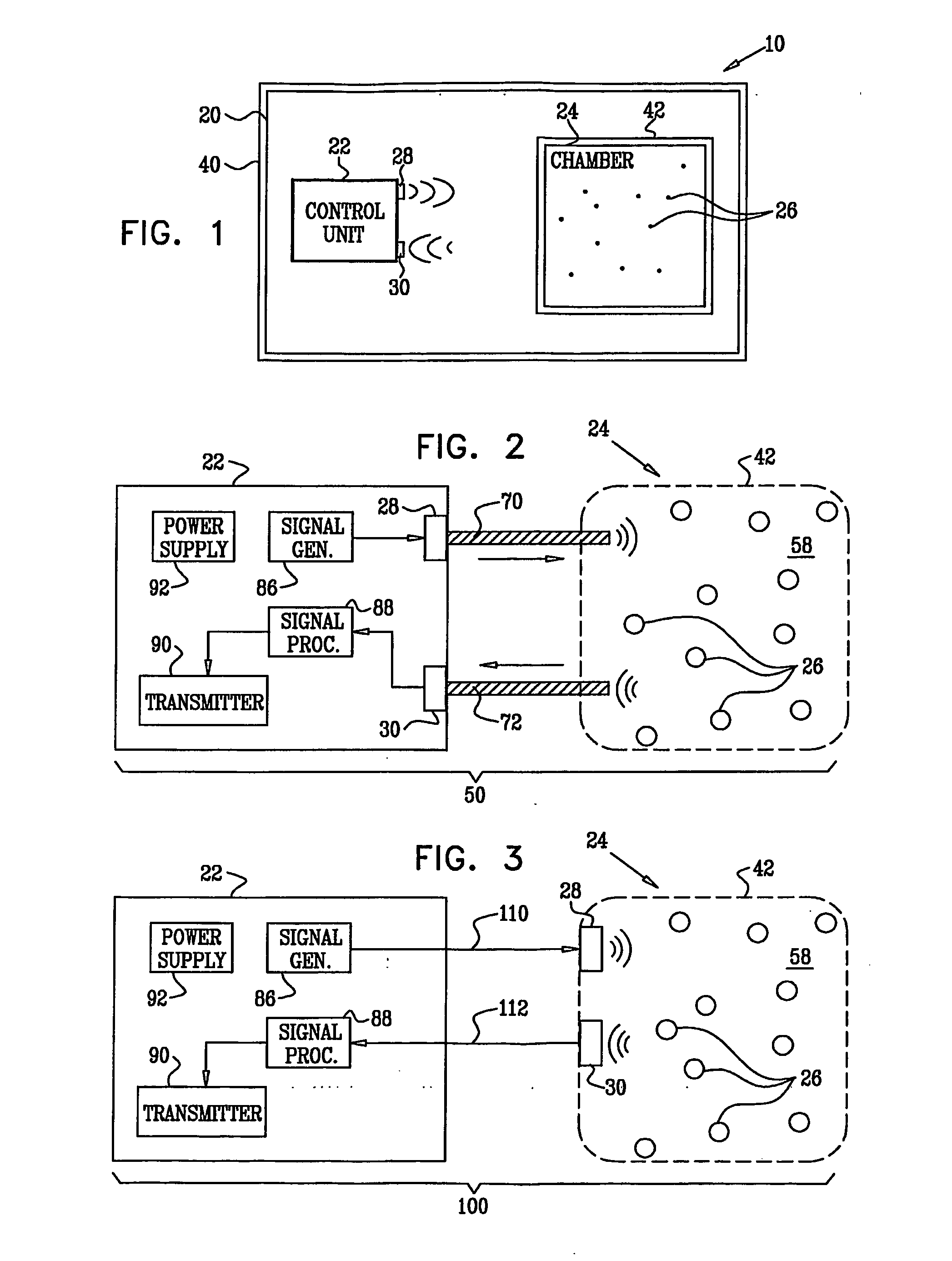
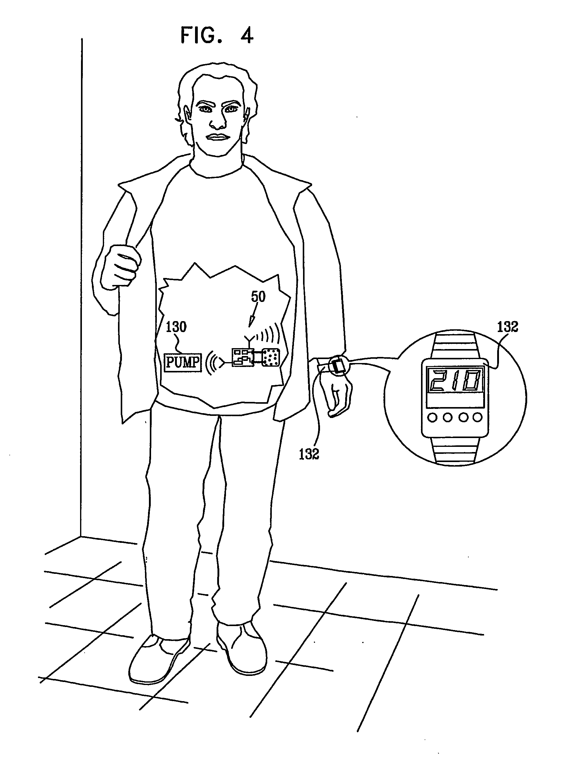
[0141]FIG. 1 is a schematic illustration of an implantable device 10 for detecting a concentration of an analyte in a subject, such as a blood constituent or other body fluid constituent of the subject, in accordance with an embodiment of the present invention. Device 10 comprises an implantable housing 20 that holds a control unit 22 and cells 26. For some applications, no housing is provided. Control unit 22 comprises a light source 28, such as a laser or an LED, and an optical detector 30, which may comprise a CCD or other suitable detector. Cells 26 are genetically engineered to produce, in a patient's body, sensor proteins comprising a fluorescent protein donor, a fluorescent protein acceptor, and a binding protein for the analyte. As appropriate, the sensor proteins may generally reside in the cytoplasm of cells 26 and / or may be targeted to reside on the cell membranes of cells 26, and / or may be secreted by cells 26 into a chamber 24. The sensor proteins are configured such th...


PUM

PropertyMeasurementUnit
Lengthaaaaaaaaaa
Concentrationaaaaaaaaaa
Resonance energyaaaaaaaaaa

Abstract

Apparatus is provided for detecting a concentration of an analyte in a subject. The apparatus includes a housing (20) adapted to be implanted in the subject. The housing (20) comprising an optical detector (30) adapted to detect a level of fluorescence resonance energy transfer (FRET). The apparatus also comprises live cells (26) genetically engineered to produce, in a patient's body, a sensor protein comprising a fluorescent protein donor, a fluorescent protein acceptor, and a binding protein for the analyte. Other embodiments are also described.

Description

CROSS REFERENCES TO RELATED APPLICATIONS[0001]The present application:[0002](a) claims priority from U.S. Provisional Patent Application 60 / 786,532 to Gross et al., filed Mar. 28, 2006, entitled, “Implantable sensor”; and[0003](b) is a continuation-in-part of International Patent Application PCT / IL2005 / 000743 to Gross et al., filed Jul. 13, 2005, entitled, “Implantable power sources and sensors,” which claims the benefit of: (i) U.S. Provisional Patent Application 60 / 658,716, filed Mar. 3, 2005, entitled, “Implantable power sources and sensors,” and (ii) U.S. Provisional Patent Application 60 / 588,211, filed Jul. 14, 2004, entitled, “Implantable sensor.”[0004]Each of the above applications is incorporated herein by reference.FIELD OF THE INVENTION[0005]The present invention relates generally to implantable sensors, and specifically to methods and apparatus for sensing blood glucose concentrations.BACKGROUND OF THE INVENTION[0006]Fluorescence resonance energy transfer (FRET) involves ...

Claims


Application Information

Patent Timeline
IPC IPC(8): A61K49/00A61B5/1459A61B5/1473A61P43/00
CPCA61B5/14532A61B5/14556C07K2319/60C07K14/43595A61B5/1459A61P43/00
Inventor GROSS, YOSSIHYMAN, TEHILA
Owner GLUSENSE LTD
Why Eureka
Eureka Blog
Learn More