Eureka AIR delivers breakthrough ideas for toughest innovation challenges, trusted by R&D personnel around the world.

Apparatus and Method with Controlled Switch Method

a technology of apparatus and method, applied in the field of embedded microcontroller systems, can solve the problems of typical os consuming power and execution time, os flexibility consumes a price in important system resources, etc., and achieves the effect of less overhead, less power, and shorter tim

Active Publication Date: 2010-07-29
TEXAS INSTR INC
View PDF12 Cites 34 Cited by
  • Summary
  • Abstract
  • Description
  • Claims
  • Application Information

AI Technical Summary

Benefits of technology

This patent describes an embedded microcontroller system that can handle task requests from hardware or software with less overhead, less power, and in less time than conventional systems. The system includes a central processing unit and a system controller that receives and handles interrupts. The system controller includes a register with predefined system data for different operating conditions of the system, which can be set through early negotiations between the operating system and the application or driver. The system controller can also transmit a selection signal to the register to select and activate the predefined system data. The system controller can also handle different kinds of exceptions, such as faults, traps, and aborts. The system controller can also contain a single register or multiple registers for different interrupt resources. The register can be locked or at least partially locked to protect its content. The system controller can also disable or enable a register for a specific interrupt request. The register can also contain a data field that defines which stack pointer will be used or controls access rights to system resources.

Problems solved by technology

This flexibility through the software of an OS consumes a price in important system resources.
Therefore, the typical OS consumes power and execution time in order to organize reliable software execution.

Method used


Image

  • Apparatus and Method with Controlled Switch Method
  • Apparatus and Method with Controlled Switch Method
  • Apparatus and Method with Controlled Switch Method

Examples


Embodiment Construction

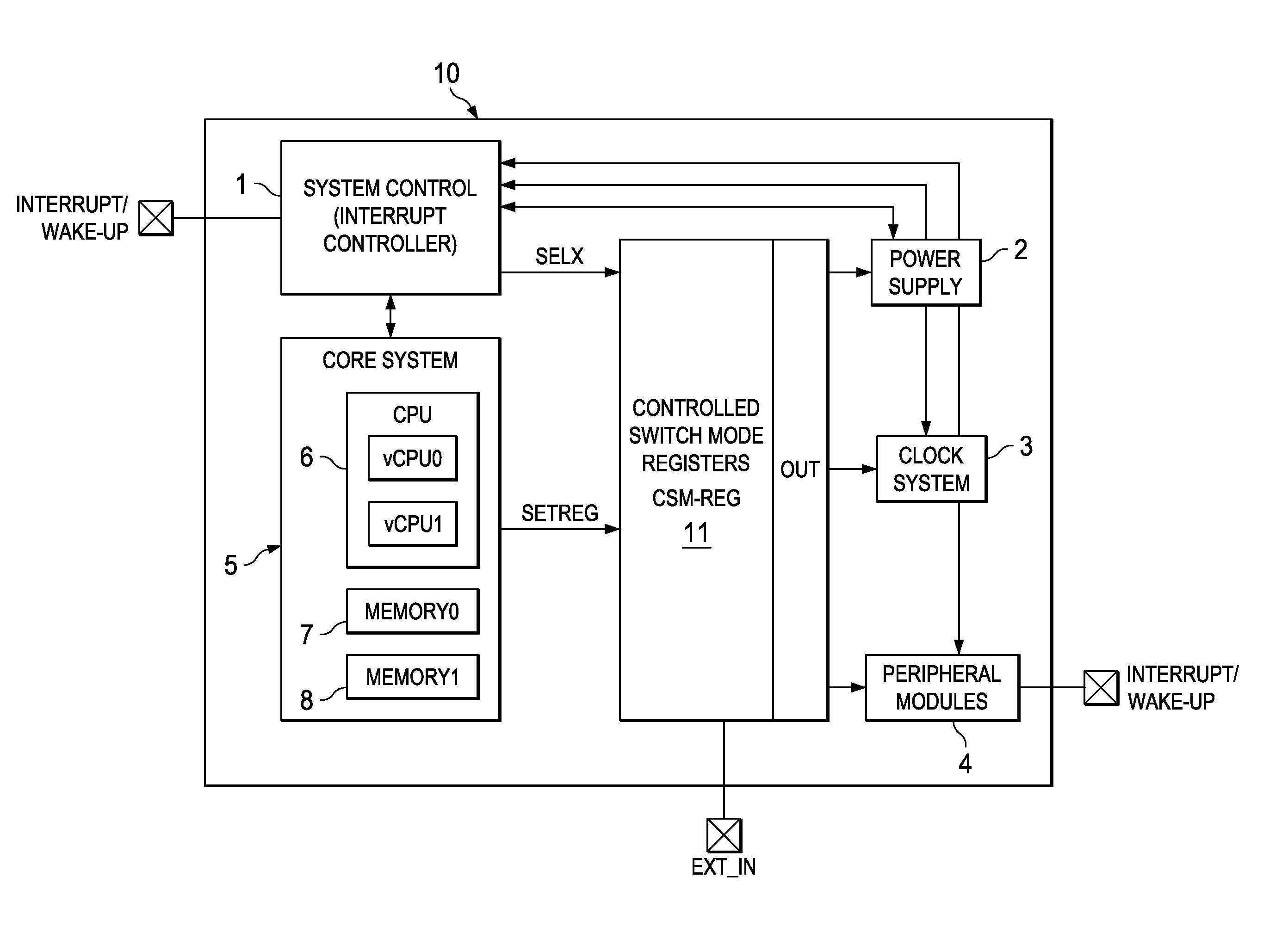
[0032]FIG. 1 is a simplified diagram of an embedded microcontroller system 10 of the prior art. Interrupt controller 1 provides the system control. Interrupt controller 1 receives interrupts or wakeup signals from other system instances implemented in hardware or software or combinations of hardware and software. Interrupt controller 1 is coupled to power supply manager 2, clock system 3, analog or digital peripheral modules 4 and core system 5. Core system 5 includes CPU 6 with virtual CPUs vCPU0 and vCPU1, and memory banks 7 and 8. Interrupt controller 1 may have variable interrupt levels, nesting capability or other features. Only very simple applications still run under the same environment without any task separation in embedded control applications. Most applications use and operating system (OS). The OS is implemented in the core system 5 of FIG. 1. For example, virtual CPU vCPU0 receives the interrupts and the OS is executed in vCPU0. The OS handles all the switching conditi...


PUM


Abstract

An embedded microcontroller system comprises a central processing unit, a system controller for receiving and handling an interrupt, a register having storage locations containing sets of predefined system data for different operating conditions of the system assigned to the interrupts coupled to set a system configuration. The system data in the register is defined and stored before receipt of an interrupt. On receipt of an interrupt the system controller transmits a selection signal to the register. The register selects a predefined storage location assigned to the received interrupt. The corresponding system configuration data is used to control system configuration of the embedded microcontroller system, such as allocation of CPU time to virtual CPUs and selection of clock frequency or power voltage for modules.

Description

CLAIM OF PRIORITY[0001]This application claims priority under 35 U.S.C. 119(a) to German Patent Application No. 10 2008 062 692.9 filed Dec. 17, 2008.TECHNICAL FIELD OF THE INVENTION[0002]The technical field of this invention is an embedded microcontroller system with a central processing unit (CPU) and a system controller and circuitry and a method for configuring the embedded microcontroller system.BACKGROUND OF THE INVENTION[0003]Controllers and computer programs use operating systems (OS) or specific derivatives of operating systems in order to react to requests for system configurations relating to hardware and software resources. Many applications especially in embedded computing need to respond precisely, in a well predefined manner and deterministically to requests from hardware and software. These requests may be sent from a communication interface, analogue components or simple a timer which triggers the software to proceed. Operating systems that require such deterministi...

Claims


Application Information

Patent Timeline
Patent Type & Authority Applications(United States)
IPC IPC(8): G06F13/24G06F1/04G06F9/50G06F1/26G06F12/14
CPCY02B60/144G06F9/4812Y02D10/00
Inventor ZIPPERER, JOHANNDIEWALD, HORST
Owner TEXAS INSTR INC
Why Eureka
Eureka Blog
Learn More