
3D image display device

a display device and image technology, applied in optics, instruments, electrical equipment, etc., can solve the problems of preventing commercial use, imposing limitations on the region within which a 3d image can be displayed, and preventing the use of 2d images by barriers, so as to minimize the effect of field-of-view overlapping

Active Publication Date: 2010-07-22
KOREA INST OF SCI & TECH
View PDF7 Cites 23 Cited by
  • Summary
  • Abstract
  • Description
  • Claims
  • Application Information

AI Technical Summary

Benefits of technology

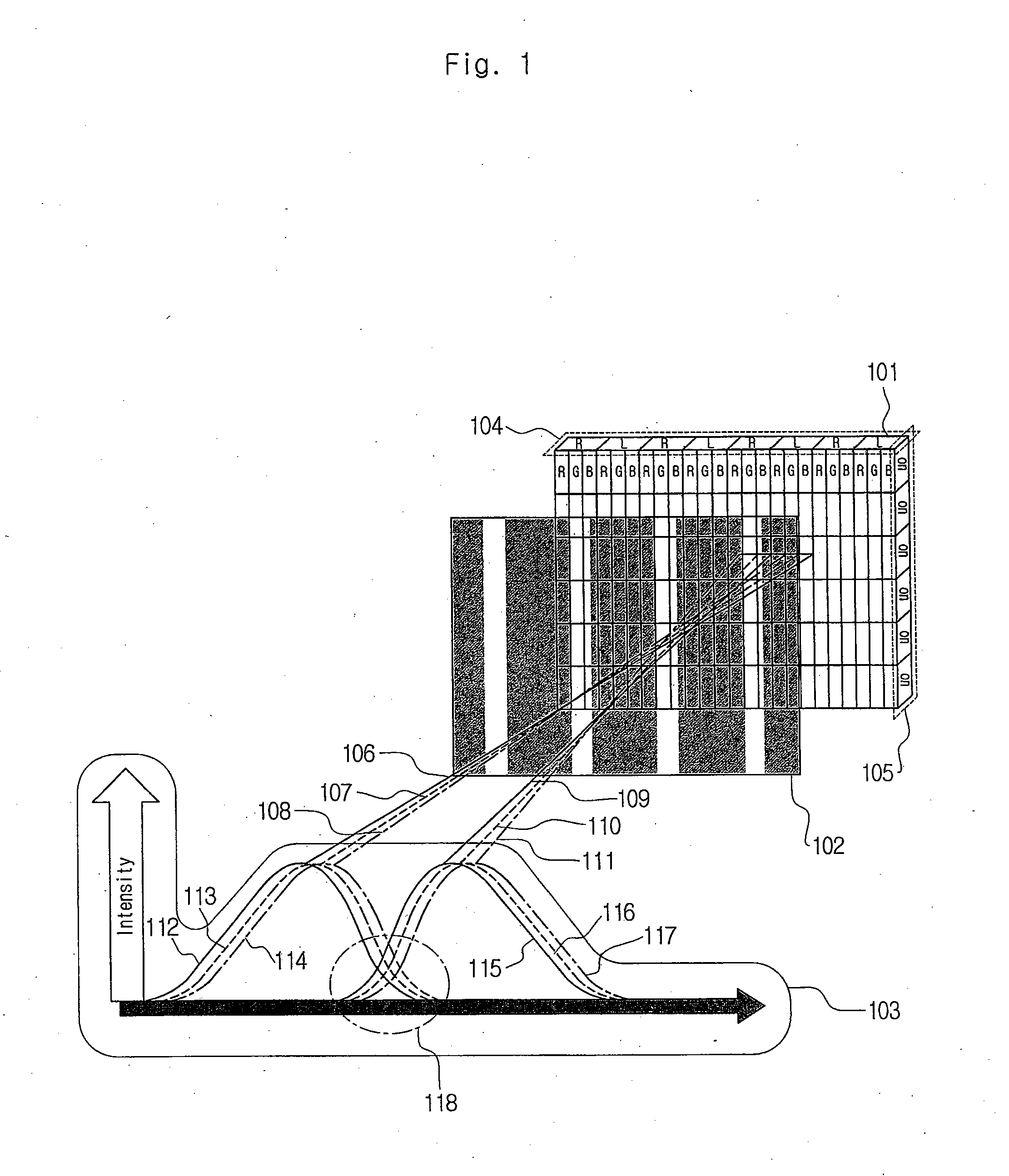
[0014]The 3D image display device disclosed herein eliminates chromatic dispersion and field-of-view overlapping effects occurring in a glasses-free 3D image display device in order for a viewer to view the 3D image precisely. Further, in case that a 2D image is represented by the 3D image display device, the device minimizes the variation of the brightness of the image.
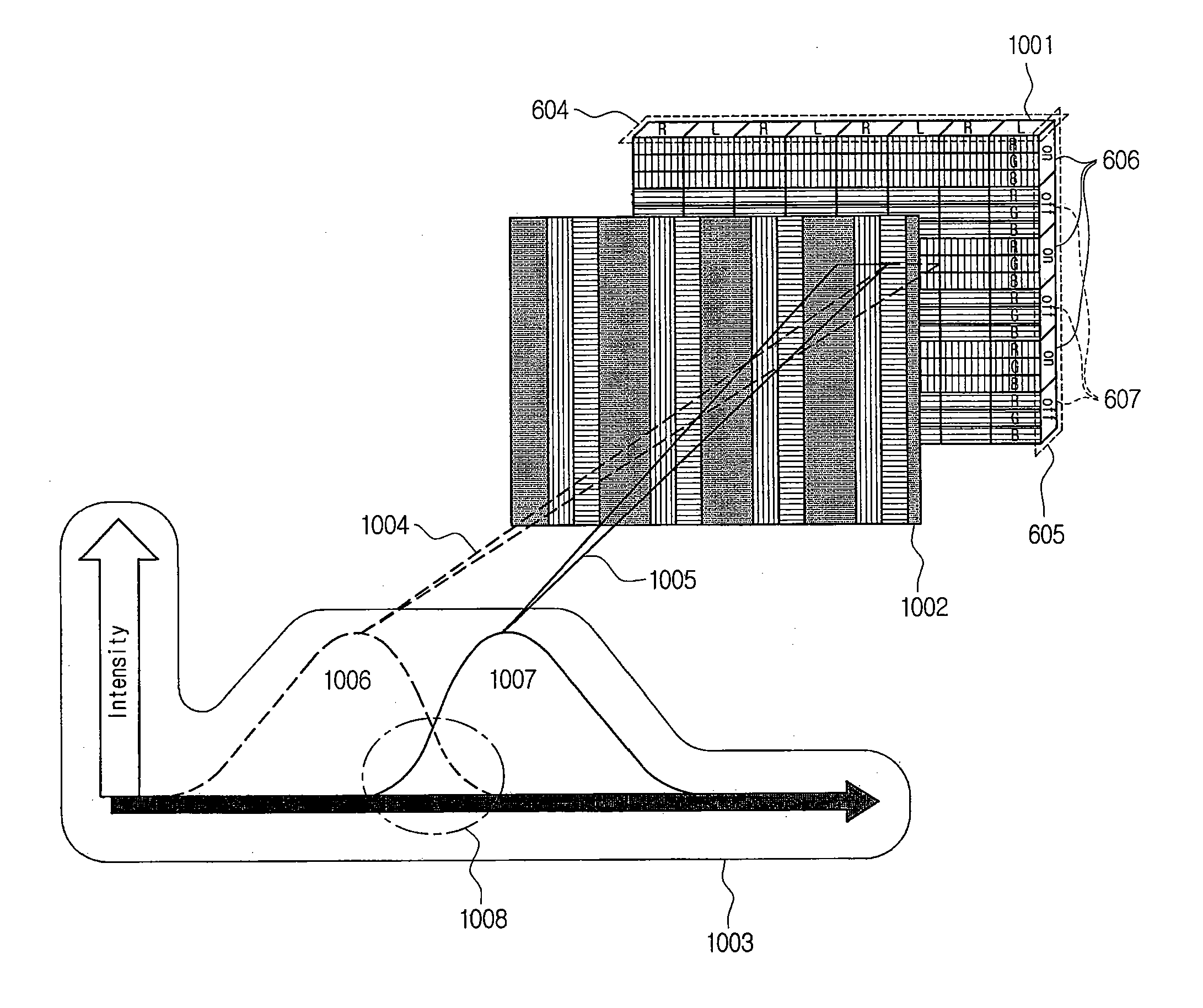
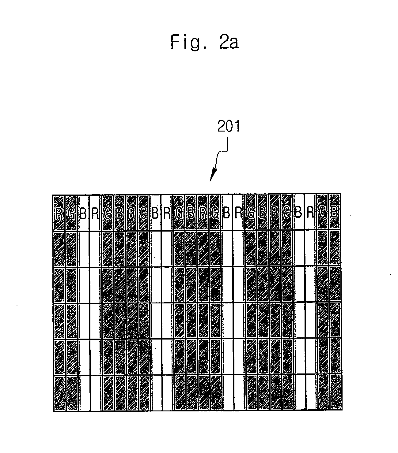
[0015]In one aspect, there is provided a glasses-free stereoscopic image display device, which includes an image display panel outputting image signals; and a parallax barrier arranged in front of the panel at a particular distance and having transparent portions repeating at particular intervals. The barrier eliminates chromatic dispersion and field-of-view overlapping effects caused by the relationship between the barrier and the panel. The image display device disclosed herein is characterized in that the arrangement of the transparent portions of the barrier, which correspond to each of views, may be modified in the vertical and horizontal directions, and the arrangement and the operation of color component units of the device may be adjusted.

Problems solved by technology

However, such displays with two views impose limitations on the region within which a 3D image may be seen.
Multiple or hypermultiple views have been introduced to improve this problem, but they require very high display resolution, or high speed display devices, preventing commercial use of them.
Moreover, the barrier method or the dynamic barrier method for virtual reality, which provide 3D images corresponding at a viewer's position using a static parallax barrier, also have problems caused by the variation of resolution depending on situations.
Further, the barrier method is not able to provide 2D images.
This method is associated with the problems of chromatic dispersion and field-of-view overlapping effects.
Usually, in case that a static parallax barrier is used for two views, the problem of chromatic dispersion, i.e. the phenomenon that each rays of pixels disperses when transmitting the barrier, occurs to prevent colors from being accurately represented.
This difference leads to chromatic dispersion, which aggravates field-of-view overlapping effects.

Method used


Image

  • 3D image display device
  • 3D image display device
  • 3D image display device

Examples


Embodiment Construction

[0041]Exemplary embodiments now will be described more fully hereinafter with reference to the accompanying drawings, in which exemplary embodiments are shown. This disclosure may, however, be embodied in many different forms and should not be construed as limited to the exemplary embodiments set forth therein. Rather, these exemplary embodiments are provided so that this disclosure will be thorough and complete, and will fully convey the scope of this disclosure to those skilled in the art. In the description, details of well-known features and techniques may be omitted to avoid unnecessarily obscuring the presented embodiments.

[0042]The terminology used herein is for the purpose of describing particular embodiments only and is not intended to be limiting of this disclosure. As used herein, the singular forms “a”, “an” and “the” are intended to include the plural forms as well, unless the context clearly indicates otherwise. Furthermore, the use of the terms a, an, etc. does not de...


PUM


Abstract

The 3D image display device disclosed herein includes an image display panel outputting image signals; and a parallax barrier arranged in front of the panel, being spaced at a particular distance, and having a plurality of transparent portions. The transparent portions of the barrier have a plurality of transverse lines, each of which forms one cycle, and the transparent portions that are adjacent to each other in the longitudinal direction in one cycle are arranged to emit images to different fields of view, respectively. The panel operates on and off by lines in the transverse direction based on views.

Description

CROSS-REFERENCE TO RELATED APPLICATION[0001]This application claims the benefit of, and priority to, Korean Patent Application No. 10-2009-0005211, filed on Jan. 21, 2009, under 35 U.S.C. §119. Korean Patent Application No. 10-2009-0005211 is herein incorporated by reference in its entirety.BACKGROUND[0002]1. Field[0003]This disclosure relates to an image display device, specifically to an image display device displaying a 3D image without field-of-view overlapping effects and chromatic dispersion.[0004]2. Description of the Related Art[0005]Glasses-free 3D displays, which do not require special glasses, are being developed. However, such displays with two views impose limitations on the region within which a 3D image may be seen. Multiple or hypermultiple views have been introduced to improve this problem, but they require very high display resolution, or high speed display devices, preventing commercial use of them. Moreover, the barrier method or the dynamic barrier method for vi...

Claims


Application Information

Patent Timeline
IPC IPC(8): G02B27/26G02B27/22G02B30/25G02B30/30
CPCG02B27/0093G02B27/2214G02B27/26G02B27/2264G02B27/22G02B30/25G02B30/30H04N13/00G02B30/27G02B30/24
Inventor KIM, SUNG KYUYOON, SEON KYU
Owner KOREA INST OF SCI & TECH
Learn More