Wind Generator with Folding Mast
a technology of wind generators and masts, applied in the direction of propellers, propulsive elements, water-acting propulsive elements, etc., can solve the problems of unsuitability, unreliable, and expensive, and achieve the effect of reducing the number of wind generators, and improving the efficiency of wind generators
- Summary
- Abstract
- Description
- Claims
- Application Information
AI Technical Summary
Benefits of technology
Problems solved by technology
Method used
Image


Examples
first embodiment
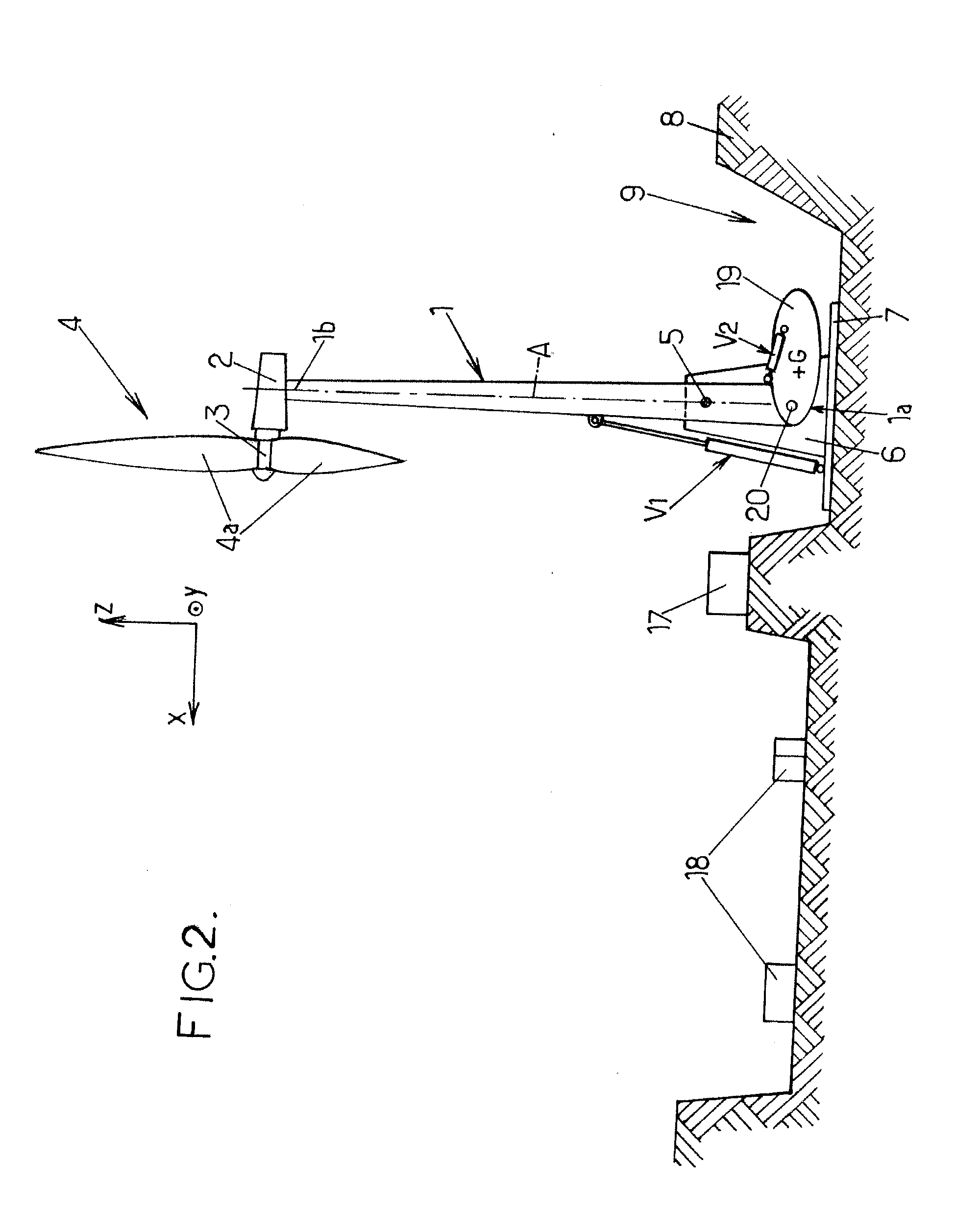
[0057]In the invention (FIGS. 1-5), the counterweight 19 is a moving counterweight, the center of gravity G of which can be positioned a variable distance from the articulation 5. In the particular example depicted, the moving counterweight 19 is pivotally mounted about an articulation 20 at the lower end 1a of the mast 1.
[0058]The moving counterweight 19 here has an elongate, for example ovalized, shape, and can be pivoted, between:[0059]the position depicted in FIG. 2 in which said moving counterweight has its longitudinal axis substantially perpendicular to the longitudinal direction of the mast 1 when said mast 1 is in the erect position,[0060]and the position of FIG. 5 in which the moving counterweight 19 has its longitudinal axis substantially in the continuation of the longitudinal axis of the mast 1 when said mast 1 is in the folded-down position.
[0061]The moving counterweight 19 can be operated by an actuator V2 such as a hydraulic ram for example, which connects said movin...
second embodiment
[0070]In the second embodiment depicted in FIG. 6, the counterweight 19 is replaced by a sliding counterweight which is made out of similar material as said counterweight 19 and which is slidingly mounted along the mast 1, for example along rails or slideways 22, in the direction of the double arrow 23 (parallel to the longitudinal axis A of the mast).
[0071]The moving counterweight 21 is controlled, for example, by a hydraulic ram V2, as in the first embodiment of the invention, so that it is moved in synchronism with the pivoting of the mast 1 so that the center of gravity G of the moving counterweight 21 progressively moves away from the articulation 5 along the longitudinal axis A of the mast when the mast 1 is pivoting into its folded-down position and, conversely, so that said center of gravity G moves progressively closer to the articulation 5 along the longitudinal axis A when the mast 1 is being erected.
[0072]The other elements of the wind generator and the operation of the ...
third embodiment
[0083]The wind generator may be operated as follows.
[0084]When the mast 1 is in the erect position as shown in FIGS. 7-9, the counterweight is pushed downward by the ram V2 so as to maintain the notches 37 of the counterweight engaged on the transverse rib 38, thereby locking the mast 1 in the erect position. The transverse rib 38 thus constitutes a fixed anchoring device with which the counterweight 27 cooperates by fitting engagement when the mast 1 is erect, in order to lock said mast in the erect position.
[0085]When the mast 1 has to be folded down, the ram V2 initially raises the counterweight 27 so that the notches 37 of the counterweight disengage from the transverse rib 38, the ram V1 pivots the mast 1 downward as shown in FIG. 10, until the mast 1 is completely folded down in the horizontal position as shown in FIG. 11.
[0086]During this process, the ram V2 is controlled so as to pivot the counterweight 27 during the pivoting of the mast, to move progressively the center of...
PUM
 Abstract
Description
Claims
Application Information
 - R&D
- Intellectual Property
- Life Sciences
- Materials
- Tech Scout
- Unparalleled Data Quality
- Higher Quality Content
- 60% Fewer Hallucinations
Browse by: Latest US Patents, China's latest patents, Technical Efficacy Thesaurus, Application Domain, Technology Topic, Popular Technical Reports.
© 2025 PatSnap. All rights reserved.Legal|Privacy policy|Modern Slavery Act Transparency Statement|Sitemap|About US| Contact US: help@patsnap.com