Tunable zero-chirp pulse generator using plasma dispersion phase modulator

a phase modulator and zero-chirp technology, applied in the field of optical signal processing, can solve the problems of modulator optical path length, chirped transmission signal, degraded spectral efficiency and long haul transport characteristics, etc., and achieve the effect of effective chirp-free rz transmission, and effective chirp-free transmission

Inactive Publication Date: 2010-07-15
RPX CORP
View PDF5 Cites 1 Cited by
  • Summary
  • Abstract
  • Description
  • Claims
  • Application Information

AI Technical Summary

Benefits of technology

[0005]Furthermore, various embodiments for generating a substantially chirp-free pulse train can be extremely efficient because the resulting pulse train peak power can be larger than the continuous wave (CW) power input into the pulse generator.
[0006]Various embodiments make it possible to generate an effectively chirp-free RZ transmission from an integrated optic platform that typically provides chirped modulation. Effectively chirp-free RZ transmission can be achieved when it previously was typically not possible in a silicon photonic based platform. By creating a chirp free transmission capability for the silicon photonics platform, new applications may be opened up for this technology.
[0007]Furthermore, electro-absorption modulator (EAM) designs in accordance with various embodiments can also be used in a platform such as indium phosphide (InP) to generate effectively chirp-free transmissions, opening up new opportunities to optimise power consumption and use of space with this technology platform.

Problems solved by technology

As is well known, chirp can degrade spectral efficiency and long haul transport characteristics.
When used for optical modulation within a push-pull Mach-Zehnder modulator (MZM), however, there is a resulting change in modulator optical path length during signal modulation that results in a chirped transmission signal.
As mentioned, modulator chirp can be detrimental to system spectral efficiency, system scalability, and transmission performance.

Method used


Image

  • Tunable zero-chirp pulse generator using plasma dispersion phase modulator
  • Tunable zero-chirp pulse generator using plasma dispersion phase modulator
  • Tunable zero-chirp pulse generator using plasma dispersion phase modulator

Examples


Embodiment Construction

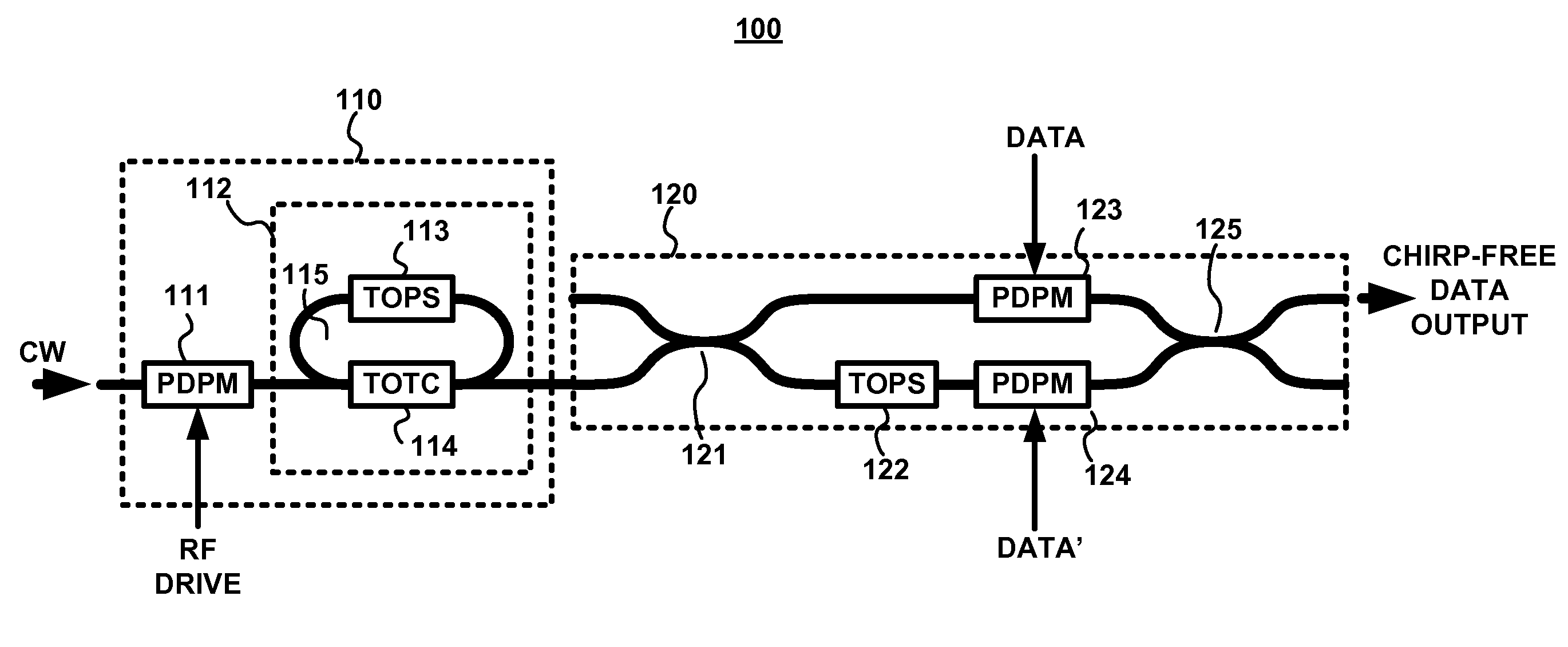
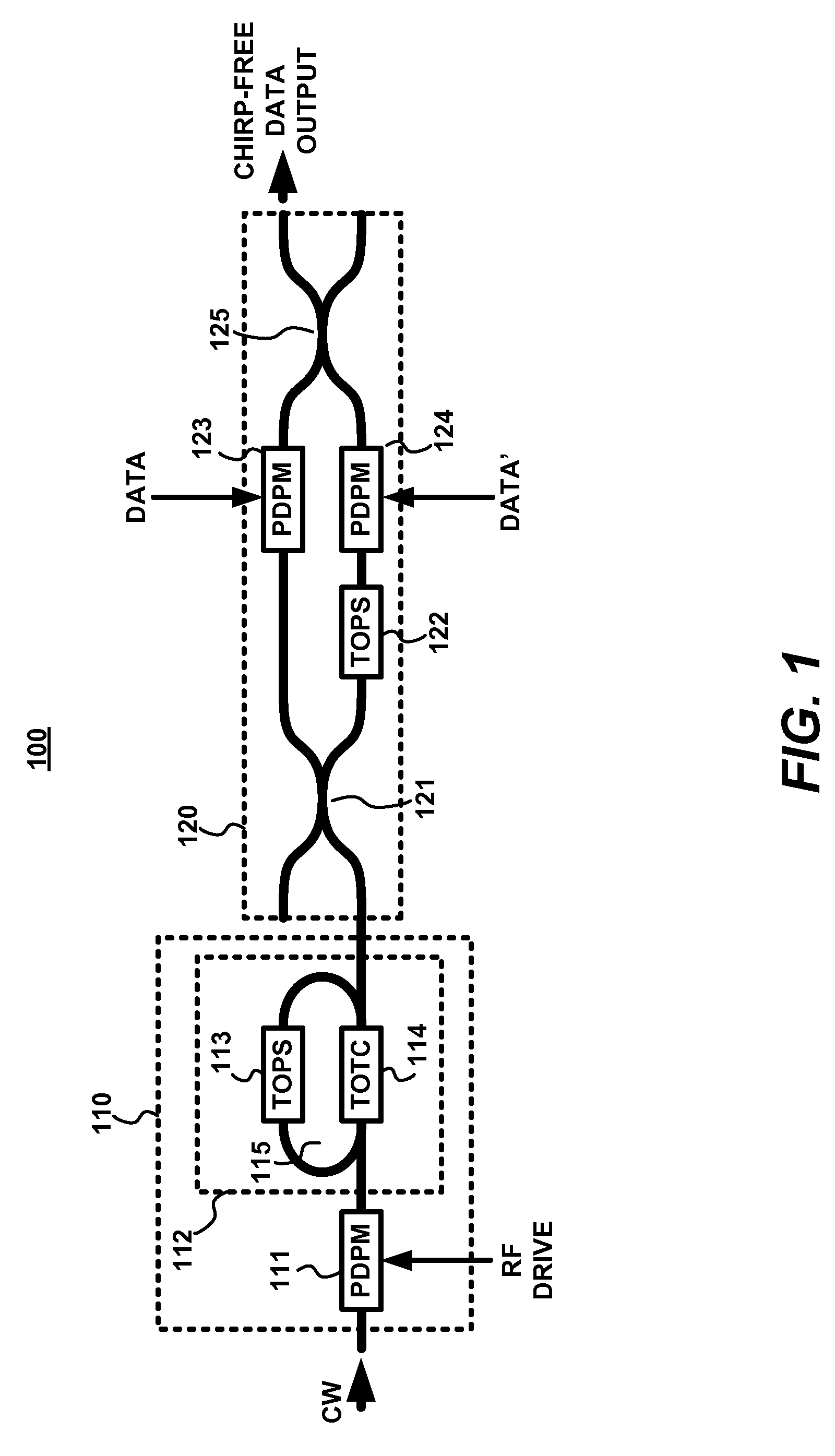
[0018]FIG. 1 is a block diagram of an exemplary embodiment of a data modulator system 100 in accordance with the present invention. The system 100 comprises an exemplary embodiment of an optical pulse generator 110 coupled to an optical modulator 120. The pulse generator 110 comprises a high-speed plasma-dispersion phase modulator (PDPM) 111 coupled to an all-pass filter (APF) 112. The APF 112 comprises a thermo-optic phase shifter (TOPS) 113 and a thermo-optic tunable coupler (TOTC) 114 arranged within a waveguide ring resonator 115. A substantially monochromatic continuous wave (CW) light signal is applied via optical waveguide to the PDPM 111 and is predominantly phase modulated thereby. As shown below, the PDPM 111 also imparts some intensity modulation to the CW light signal.

[0019]As described in greater detail below, the pulse generator 110 can generate a pulse train that is substantially chirp-free (e.g., having a chirp factor ≦±0.2), even though it is implemented using fabri...


PUM

PropertyMeasurementUnit
frequenciesaaaaaaaaaa
lengthaaaaaaaaaa

Abstract

An optical pulse generator comprising a phase modulator, wherein the phase modulator is configured to phase modulate and intensity modulate a continuous wave (CW) light signal in accordance with a received electrical signal, and an all-pass filter, the all-pass filter being coupled to the phase modulator to generate a pulsed light signal by filtering the modulated light signal from the phase modulator.

Description

FIELD OF THE INVENTION[0001]The present invention relates to the field of optical signal processing, and more specifically to apparatus and methods related to optical signal modulation.BACKGROUND INFORMATION[0002]Silicon photonics has the potential to change many aspects of data transport, but has not yet substantially impacted long haul transport. Part of the reason for this is that modulators in this platform are “chirped” in the sense that they generate signals that exhibit chirp. As is well known, chirp can degrade spectral efficiency and long haul transport characteristics.[0003]In silicon and indium phosphide (InP) photonic integrated circuits, electro-optic modulators can create optical phase shifting by using the Kramers-Kronig effect, where a change in optical loss induces a change in optical path length within an optical waveguide. This approach is effective in creating an electro-optic response, often referred to as the plasma-dispersion effect, in materials that do not h...

Claims


Application Information

Patent Timeline
Patent Type & Authority Applications(United States)
IPC IPC(8): G02F1/01
CPCH04B10/5053H04B10/5162H04B10/508
Inventor GILL, DOUGLAS M.
Owner RPX CORP
Why Eureka
Try Eureka