Data distribution system, key management device, and key management method
a data distribution system and key management technology, applied in data switching networks, digital transmission, securing communication, etc., can solve the problem of limited number of receiving terminals manageable under representative terminals, and achieve the effect of efficiently multi-casting encrypted broadcast messages and reducing traffic for updating
- Summary
- Abstract
- Description
- Claims
- Application Information
AI Technical Summary
Benefits of technology
Problems solved by technology
Method used
Image
Examples
first embodiment
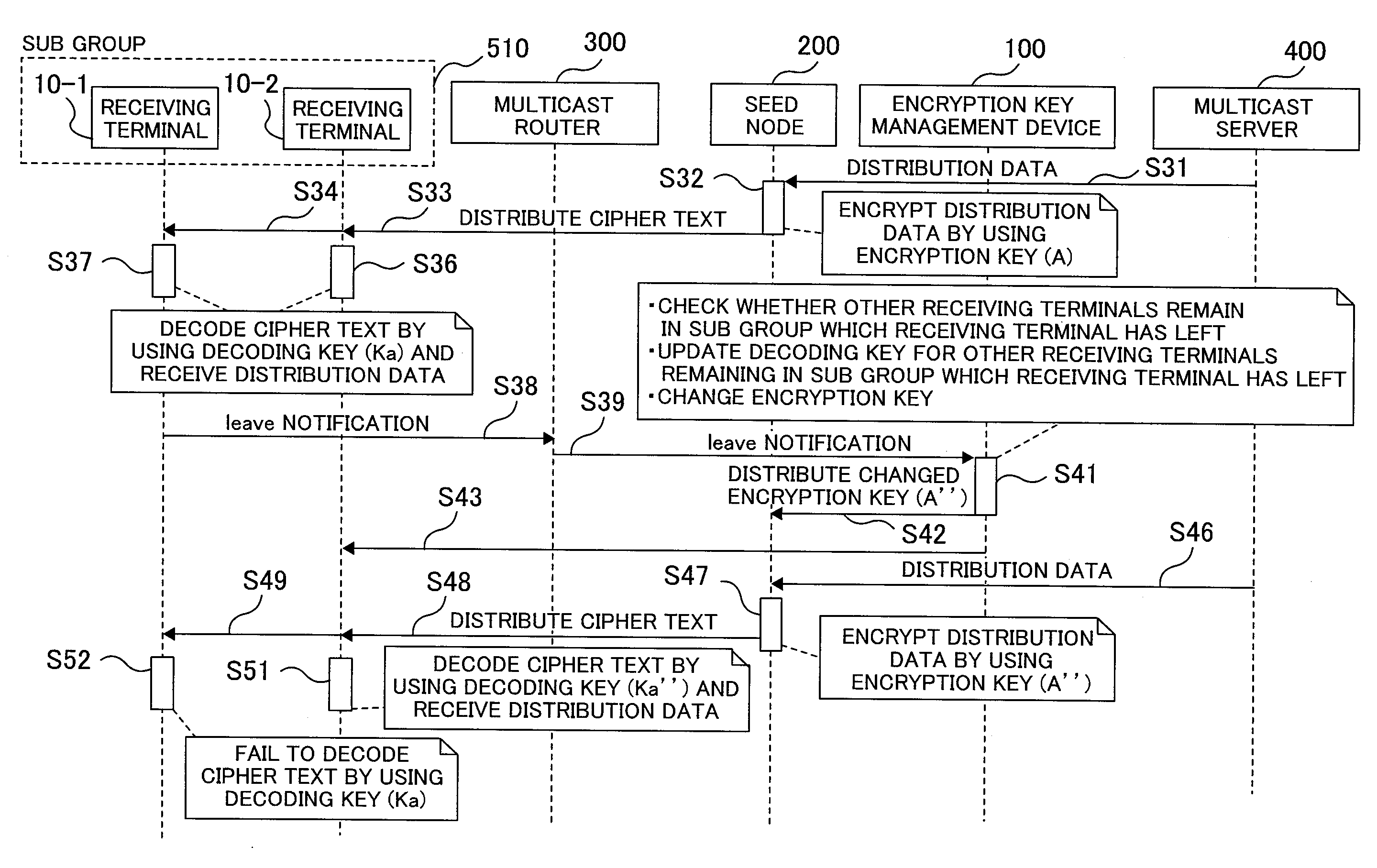
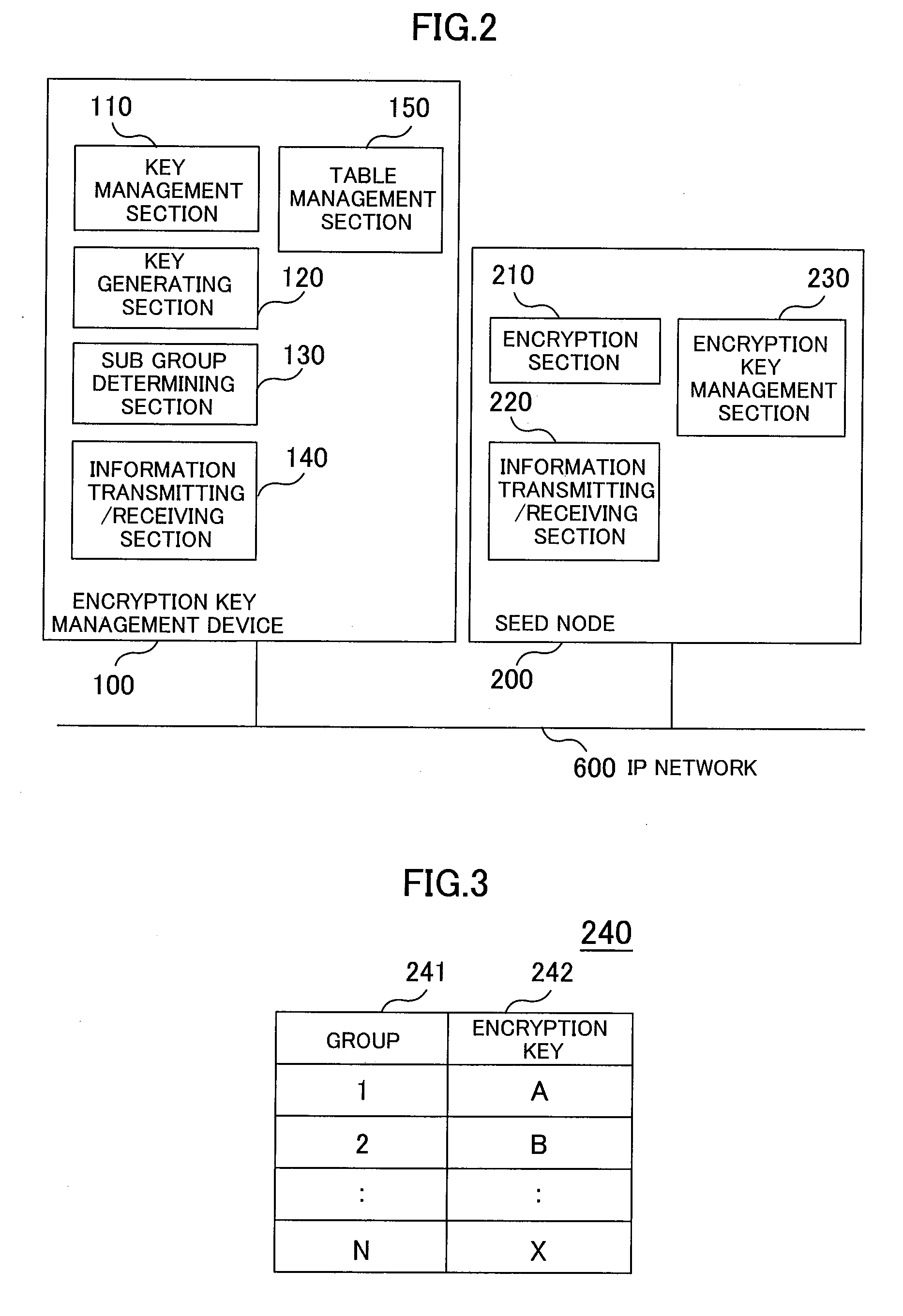
[0036]Referring to FIGS. 1 to 10, a first embodiment will be described below. FIG. 1 is a hardware block diagram showing a multicast network. FIG. 2 is a function block diagram showing a seed node and an encryption key management device. FIG. 3 is an explanatory drawing showing an encryption key management table. FIG. 4 is an explanatory drawing showing an encryption key / decoding key management table. FIG. 5 is a sequence diagram showing the creation of a new sub group among a receiving terminal, a multicast node, the seed node, the encryption key management device, and a multicast server. FIG. 6 is a sequence diagram showing the participation of a new receiving terminal, among the receiving terminal, the multicast node, the seed node, the encryption key management device, and the multicast server. FIG. 7 is a flowchart showing the participation of a new receiving terminal of the encryption key management device. FIG. 8 is a sequence diagram showing the separation of the receiving t...
second embodiment
[0075]Referring to FIG. 11, a second embodiment will be described below. FIG. 11 is a hardware block diagram showing a multicast network.
[0076]In FIG. 11, a multicast network 1000A is made up of a multicast server 400, a seed node 200, a key management device 100, multicast routers 300, and receiving terminals 10. The configuration of the second embodiment is similar to that of the first embodiment. The second embodiment is characterized by a device for determining sub groups. As a method of determining the sub groups when a multicast group is divided into n sub groups, there are available: a method of randomly allocating the receiving terminals joining the multicast group to n sub groups, and a method of sequentially allocating the receiving terminals to the n sub groups. In another method, the maximum number of receiving terminals storable in a single sub group is set. In this case, when the number of receiving terminals exceeds the maximum number, another sub group is created to ...
third embodiment
[0083]Referring to FIG. 12, a third embodiment will be described below. FIG. 12 is a sequence diagram showing a multicast network. When a multicast group has n sub groups, the sub groups has prime numbers K1, K2, . . . , Kn larger than a numeric value M representing data to be distributed from a multicast server. In the case of large data, the data may be divided into pieces of proper sizes and one of the divided pieces of data may be processed as M as will be described below. An encryption key A is expressed as A=K1*K2* . . . *Kn, the decoding key of a sub group 1 is denoted as K1, the decoding key of the sub group 2 is denoted as K2, and the decoding key of a sub group n is denoted as Kn. The number of decoding keys is equal to the number of sub groups.
[0084]Encryption is performed according to (equation 18).
X=M+A (equation 18)
where X is cipher text.
[0085]However, in order to protect the multicast group from others, it is necessary to achieve stronger encryption for cipher text ...
PUM
 Abstract
Description
Claims
Application Information
 - R&D
- Intellectual Property
- Life Sciences
- Materials
- Tech Scout
- Unparalleled Data Quality
- Higher Quality Content
- 60% Fewer Hallucinations
Browse by: Latest US Patents, China's latest patents, Technical Efficacy Thesaurus, Application Domain, Technology Topic, Popular Technical Reports.
© 2025 PatSnap. All rights reserved.Legal|Privacy policy|Modern Slavery Act Transparency Statement|Sitemap|About US| Contact US: help@patsnap.com


