
Digital signal processing circuit and method comprising band selection

Active Publication Date: 2010-07-08
NXP BV
View PDF12 Cites 10 Cited by
  • Summary
  • Abstract
  • Description
  • Claims
  • Application Information

AI Technical Summary

Benefits of technology

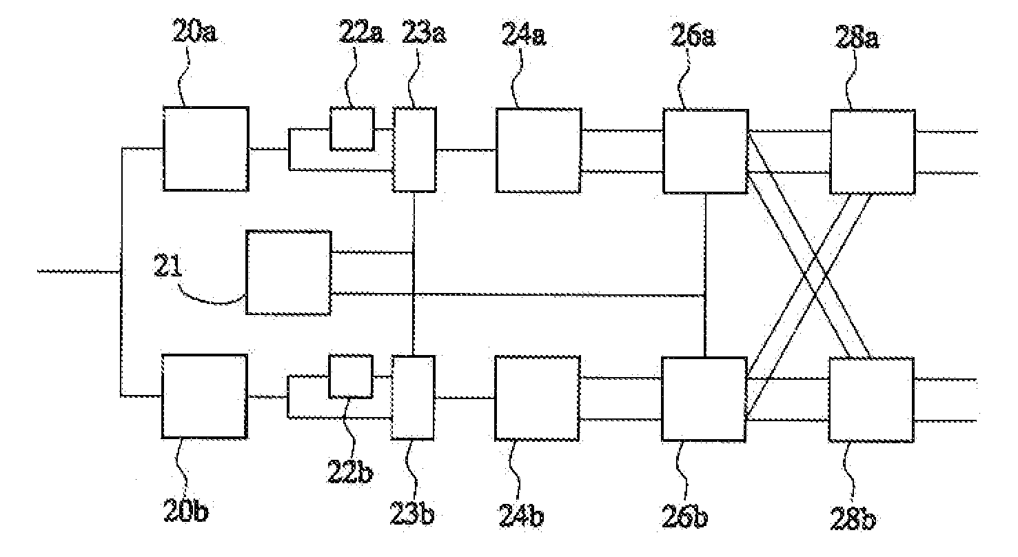
[0009]According to one aspect a digital signal processing circuit according to claim 1 is provided. Herein mixing plus filtering is implemented in a number of processing branches that use cyclically changing combination patterns to combine outputs of different FIR filters into output signals of each branch. The FIR filters are applied to mutually complementary subsets of sub-sampled values. This approach implies that band selection is performed for only for bands with selected band frequencies, such as a band centred at a frequency of one eight of the sampling frequency. In this way the amount of computations is reduced. Bands linked to other even fractions of the sampling frequency may be used.
[0011]In an embodiment the circuit comprises a selectable inverter in front of the filters, which operates according to a pattern wherein each time two successive samples are inverted and then the next two samples are not inverted. By using an inverter at this location the required amount of computation may be reduced.
[0012]In an embodiment a plurality of digital channel selections may be applied to the output signal of the band selector in parallel. Thus the band selector may be used to make simultaneous digital reception of a plurality of channels feasible.
[0013]In an embodiment the circuit the filters have coefficients that make the sub-bands of the circuit overlap. This makes it easier to decode channels at the edge of the sub-band.

Problems solved by technology

The document notes that this type of digital process suffers from spurious signals, due to rounding errors in the digital local oscillator signal.
This reduces rounding errors, but it makes it impossible to tune the local oscillator to arbitrary channel frequencies.
The sample rate that can be handled by digital signal processing is limited by the ability of digital signal processing circuits to perform the required operations.
However, in this way the maximum sample rate is increasingly limited as the processing operation becomes more complex.
Unfortunately, use of parallel components drives up circuit cost.
Moreover digital signal processing circuits that are able to perform such processing tend to consume a lot of power.

Method used


Image

  • Digital signal processing circuit and method comprising band selection
  • Digital signal processing circuit and method comprising band selection
  • Digital signal processing circuit and method comprising band selection

Examples


Embodiment Construction

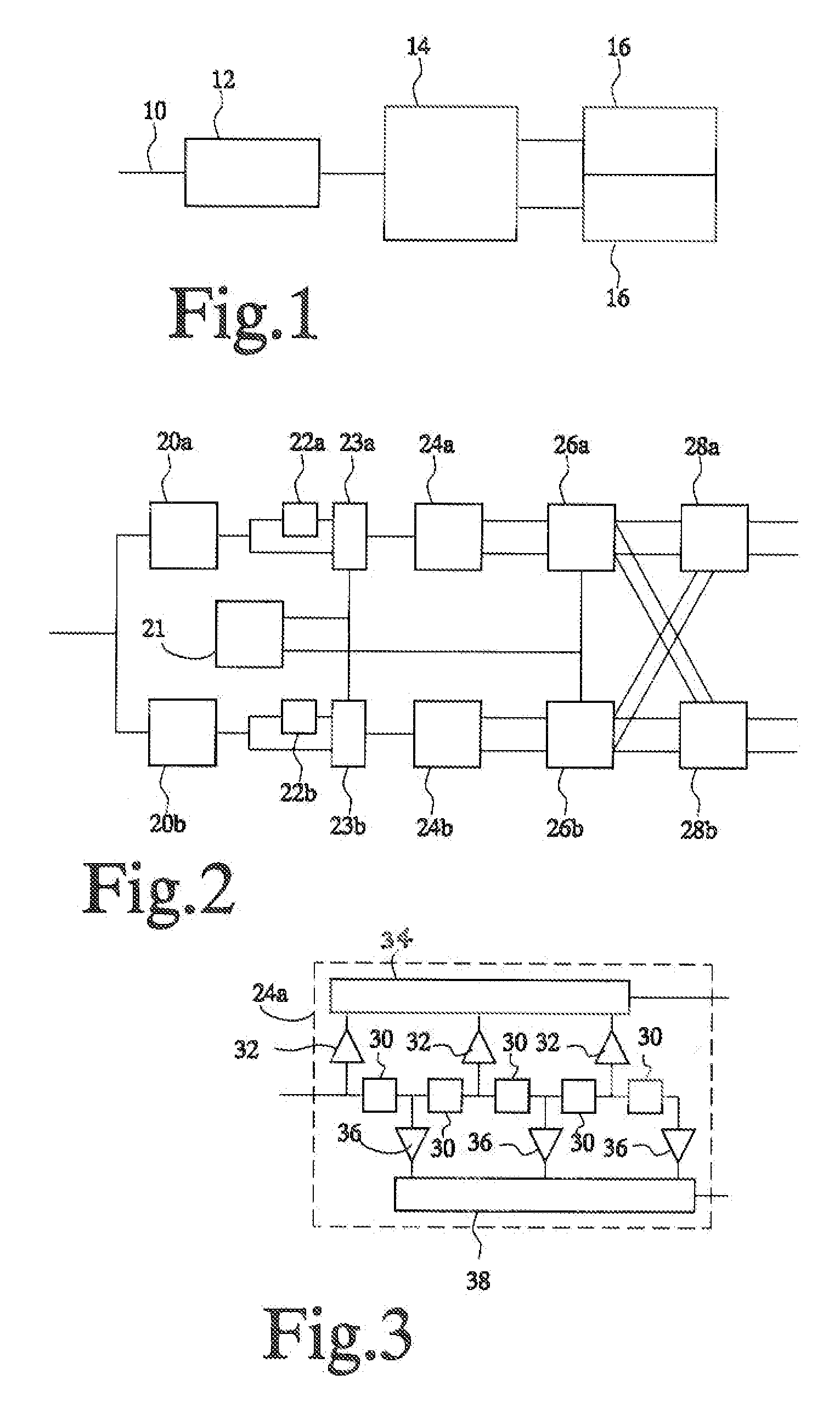
[0020]FIG. 1 shows a receiver circuit, comprising an input terminal 10, an analog to digital conversion circuit 12, a multi-band selector 14, and further processing circuits 16. Input terminal 10 may be coupled to an antenna (not shown), to an optical detector or any other signal detector, optionally via a pre-amplifier (not shown), or other analog pre-processing circuit. Input terminal 10 is coupled to an input of analog to digital conversion circuit 12. An output of analog to digital conversion circuit 12 is coupled to an input of multi-band selector 14. Multi-band selector 14 has outputs coupled to respective ones of further processing circuits 16. Although a two-way band split is shown, with two further processing circuits 16, it should be appreciated that an n-way split, with n greater than two may be used, with a corresponding number of further processing circuits 16.

[0021]In operation analog to digital conversion circuit 12 produces data that represents a stream of digitized ...


PUM


Abstract

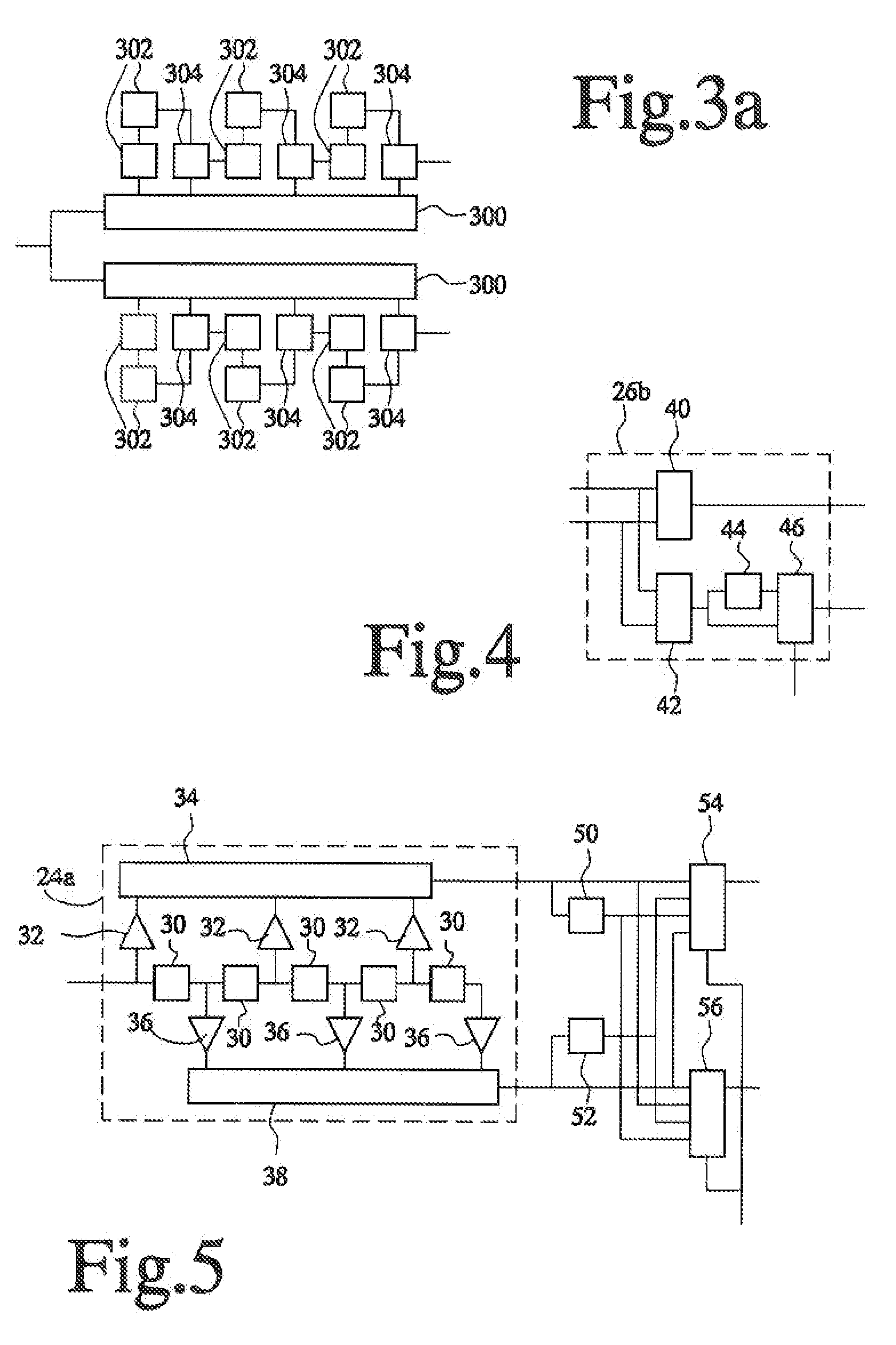
A digital signal processing circuit comprises a band selector (14) for selecting at least one sub-band from a frequency spectrum of a digital sampled input signal. The band selector (14) comprises a plurality of processing branches corresponding to respective phases and an adder (28a, 28b) for adding branch signals from the branches. Each branch comprises a subsampler (20a,b) for sub-sampling sample values of the input signal at the phase corresponding to the branch, a filter (24a,b) with a first FIR filter (32, 34), applied alternatingly to sets of even and to sets of odd samples from the subsampler (20a,b) and a second FIR filter (36, 38) applied to further sets of odd and even samples from the subsampler (20a,b) when the first FIR filter is applied to the even and odd sets respectively. Output samples from the first and second FIR filter (24a,b) are combined to form the branch signals of the branch, according to a changing combination pattern that changes cyclically as a function of sample position and depends on a phase for which the branch is used.

Description

FIELD OF THE INVENTION[0001]The invention relates to digital signal processing device and method. An embodiment relates to a digital signal device for selecting channels from a plurality of channels in a received signal.BACKGROUND OF THE INVENTION[0002]US patent application No 2002 / 0048325 describes a channel selection circuit with a digital down converter. Down conversion, which is also known from analog channel selection circuits, involves multiplying an input signal with a local oscillator signal and filtering the intermediate frequency signals. US patent application No 2002 / 0048325 describes a digital from of this process wherein a digitized signal is down-converted by digitally multiplying it with quadrature components of a digital local oscillator signal. The real and imaginary parts of the down-converted signals are passed through digital filters with the same low pass filter response. The document notes that this type of digital process suffers from spurious signals, due to ...

Claims


Application Information

Patent Timeline
IPC IPC(8): G06F17/17
CPCH03D3/006H03H2218/04H03H2017/0247H03H17/06
Inventor JANSSEN, ERWIN
Owner NXP BV
Learn More