Method and device for operating a control unit

Inactive Publication Date: 2010-07-08
ROBERT BOSCH GMBH
View PDF3 Cites 8 Cited by
  • Summary
  • Abstract
  • Description
  • Claims
  • Application Information

AI Technical Summary

Benefits of technology

[0007]A method for operating a control unit according to the present invention has the advantage that the driver may continue driving without restrictions. Due to the fact that, when the error signal for a first pair of execution units occurs, the control unit is shut down and the computer system continues to operate using the second pair of execution units and a pre-warning signal is output to the driver, the core function of the control unit being maintained while the driver receives only a warning. This method is always advantageously usable when the two pairs are so-called “lockstep pairs” which means that two execution units of one pair always process the same program steps and the output signals of the two execution units, which form one pair, are compared. The two execution units of one pair may be interconnected asynchronously or with the aid of a clock-pulse offset which is taken into account during the comparison.
[0011]In one embodiment, the second, still active pair of execution units is informed about the error in the first pair of execution units, the second pair of execution units initiating the output of the pre-warning signal. There is the option that the second pair of execution units may access various units of the computer system, thereby making it possible to use signaling devices which are already present in the vehicle and are not needed during driving operation.
[0012]In one refinement, the first pair of execution units is tested after the error has been detected and the pre-warning signal is output to the driver only when the first pair of execution units has been shut down after the error was confirmed. This has the advantage that error signaling to the driver takes place only when it is certain that a hardware error really exists and the first pair of execution units must be shut down. Transient errors, which influence the execution units by EMV effects, radioactive, or cosmic radiation, do not result in error signaling because they do not leave any permanent damage and occur only sporadically.
[0013]The occurrence of the error signal is advantageously counted and the pre-warning signal is only output when a predefined number of error signals has been ascertained. A signal is not triggered at the first occurrence of an error signal, because it is not certain in this case whether a permanent error really exists. In this way, the pair which is affected by transient errors may return to its normal processing state after the cessation of the transient errors. Disturbing of the driver by a premature error display is thus prevented. In one embodiment, the error signal is memorized, the first pair of execution units being tested at a restart of the computer system and the pre-warning signal being suppressed when the error signal fails to occur. The computer system is restarted normally when the vehicle engine is started, i.e., in a new driving cycle. After the shutdown pair of execution units is regenerated during the vehicle standstill or a vehicle reset, a warning to the driver may be omitted.
[0020]In one refinement, a memory unit containing a counter is connected to the data line, the counter being incremented by a certain value when the error signal is output by one of the two comparing units and the signaling device is only activated by the counter when a predefined counter value is reached. To prevent transient errors from occurring and to be sure that a hardware fault which is permanently repeated is present, the driver is alerted only when a predefined counter value is reached.

Problems solved by technology

The driver must stop the driving operation of the vehicle immediately, since the safety of the vehicle is no longer ensured.
A signal is not triggered at the first occurrence of an error signal, because it is not certain in this case whether a permanent error really exists.
This measure ensures that a vehicle unsuitable for driving, which does not meet the prevailing safety requirements, is not operated.
Even if it is not definitely known which errors resulted in the entries in the error memory, it must be assumed that, starting from a predefined number of error entries which have been registered either currently or within a certain period, the vehicle's safety is no longer ensured.

Method used


Image

  • Method and device for operating a control unit
  • Method and device for operating a control unit
  • Method and device for operating a control unit

Examples


Embodiment Construction

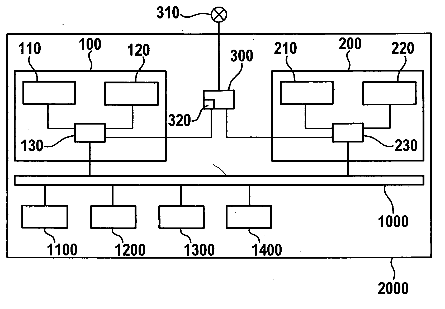
[0029]FIG. 1 shows a control unit 2000 for a motor vehicle which includes a computer system having four computing units 110, 120, 210, 220. Two [of the four] computing units 110, 120, 210, 220 are combined in a pair 100, 200. Computing units 110, 120 form pair 100 and computing units 210, 220 form pair 200.

[0030]Computing units 110, 120 of first pair 100 are connected to a first comparing unit 130, while computing units 210, 220 of second pair 200 are connected to a second comparing unit 230. First comparing unit 130 and second comparing unit 230 are connected to a communication line 1000. A memory 110 and additional peripheral units 1200, 1300, and 1400 are connected to communication line 1000.

[0031]Furthermore, comparing units 130, 230 of both pairs 100, 200 are connected to a holding element 300 which in turn is connected to a warning device 310. Warning device 310 includes two lamps, one yellow and one red.

[0032]In addition, a counter 320 is contained in holding element 300 whic...


PUM


Abstract

A control unit has two pairs of execution units, the two execution units of each pair redundantly processing the same program, and the output signals of each execution unit of one pair being compared to one another by a respective comparing unit, the respective comparing unit outputting an error signal when a difference in the output signals of the execution units of one pair occurs. A first pair of execution units are shut down when the error signal occurs for the first pair, and the control unit continues control operation using the second pair of execution units, and a pre-warning signal is output to the driver.

Description

BACKGROUND OF THE INVENTION[0001]1. Field of the Invention[0002]The present invention relates to a method for operating a control unit in a motor vehicle having a computer system which has two pairs of execution units, the two execution units of each pair processing the same program and the output signals of the execution units of one pair being compared with each other, an error signal being output in the event of a difference in the output signals of the execution units of one pair.[0003]2. Description of Related Art[0004]Published international patent application WO 2007 / 017381 A1 discloses a device which includes a multiprocessor system having four execution units, two execution units always processing the same tasks and processes. Using a comparing unit, the output signals output by two execution units, which process the same programs, are compared and when these two output signals differ from one another, an error signal is output. This case, referred to as lockstep mode, is p...

Claims


Application Information

Patent Timeline
IPC IPC(8): G01M17/00
CPCG06F11/165G06F11/1645G06F11/1695
Inventor MUELLER, BERNDFERCH, MARKUSCOLLANI, YORCK VONBANSKI, HOLGER
Owner ROBERT BOSCH GMBH
Why Eureka
Try Eureka