Recording device

Inactive Publication Date: 2008-02-12
CANON KK
View PDF26 Cites 4 Cited by
  • Summary
  • Abstract
  • Description
  • Claims
  • Application Information

AI Technical Summary

Benefits of technology

[0014]More specifically stated, it is a first object of this invention to provide a picture image recording device for recording still picture images which can be operated to record moving objects and is thus advantageously usable for many purposes.
[0016]In a preferred embodiment of this invention which will be further described hereinafter, the device is arranged to be shiftable between two different speeds in the above stated second mode. In another embodiment, the device can be used for video recording at an ordinary video recording speed through a combined use of it with a video recording device. These arrangements further enhance the functional capability of a device of this type.
[0017]It is a second object of this invention to provide a picture image recording device of the above stated type having an improved feature that double recording on a recording medium, i.e. recording on a recorded track, can be effectively prevented.
[0019]In this arrangement of the device, the inconvenience of having double recording is prevented by giving a warning against double recording and automatically prohibiting it with an output of the detecting means utilized therefor. Further, in the case of a preferred embodiment of the invention which will be described hereinafter, there is provided a control means which controls shifting of the track of a recording means (change-over from one recording track to another) in response to the output of the detecting means; and the recording track of the recording means is automatically shifted by the control means to a track which has not been recorded. This is very advantageous for a device of this type.
[0020]It is a third object of this invention to provide a picture image recording device equipped with a simple, reliable and inexpensive arrangement to automatically indicate the number of tracks of a recording medium which have been already recorded.

Problems solved by technology

Considering applications of the device of this type, if it is only possible to record more than just one picture image by each trigger operation, the function of the device is not always satisfactory and is thus applicable only to a limited range of purposes.
Without such discernment, if another picture image is recorded on the recorded track, two picture image signals would be mixed and a reproduced picture image would be hardly acceptable because, in the device of this type, it is extremely difficult to precisely align the heads of two picture image signals for synchronization and synchronism tends to be lost.
If such indication is arranged to be made by directly detecting up to which of the recording tracks recording has been performed and to show the number of recorded tracks according to the result of such detecting, the device must have a complex structure, which then would hinder an effort to make the device compact.
However, this method is not completely satisfactory because it still unnecessarily complicates the structural arrangement and also might cause an erroneous action when the device is reloaded with the cartridge.

Method used


Image

  • Recording device
  • Recording device
  • Recording device

Examples


Embodiment Construction

[0040]Referring to the accompanying drawings, preferred embodiments of the invention are described by way of example as shown below:

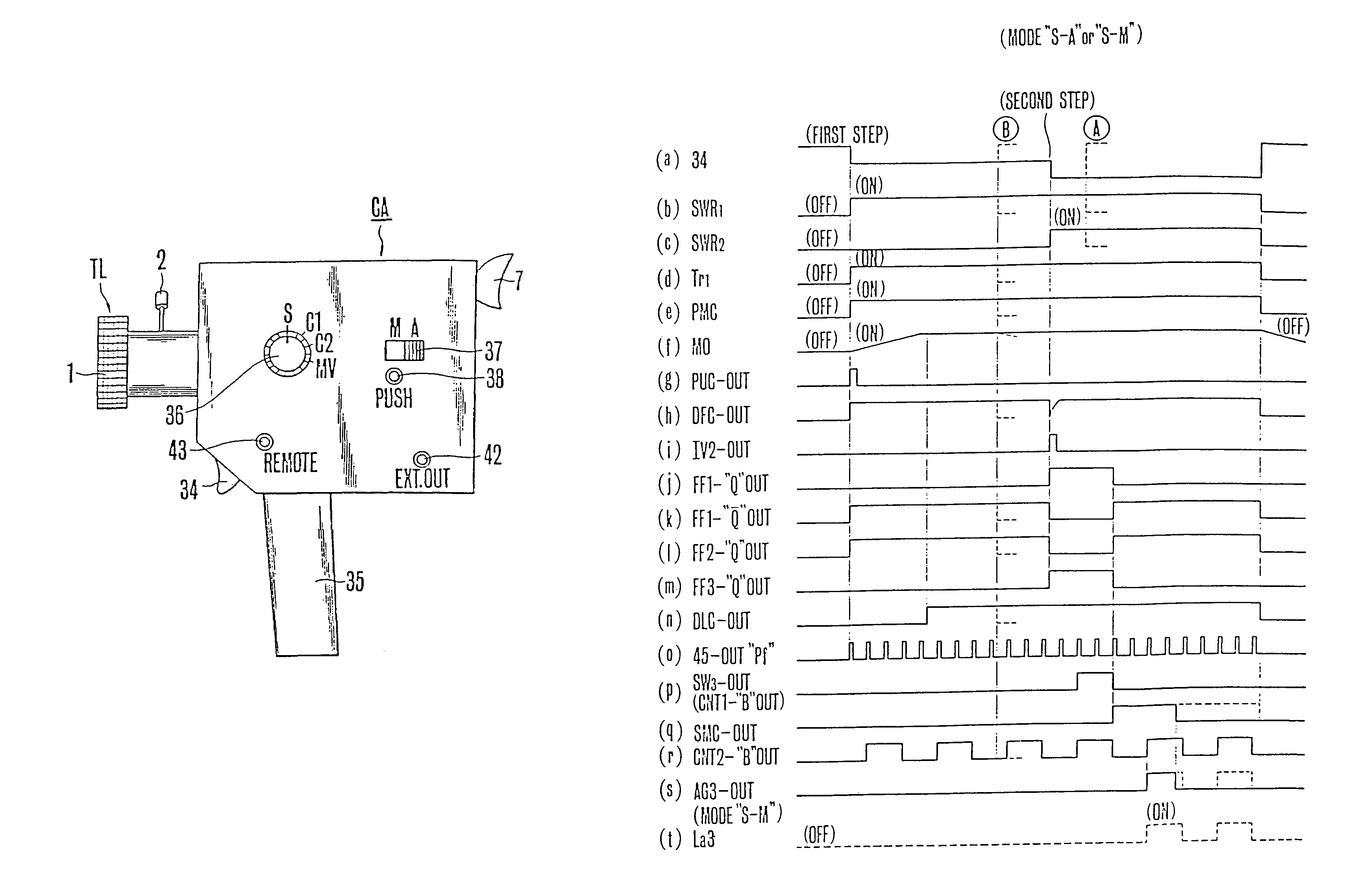
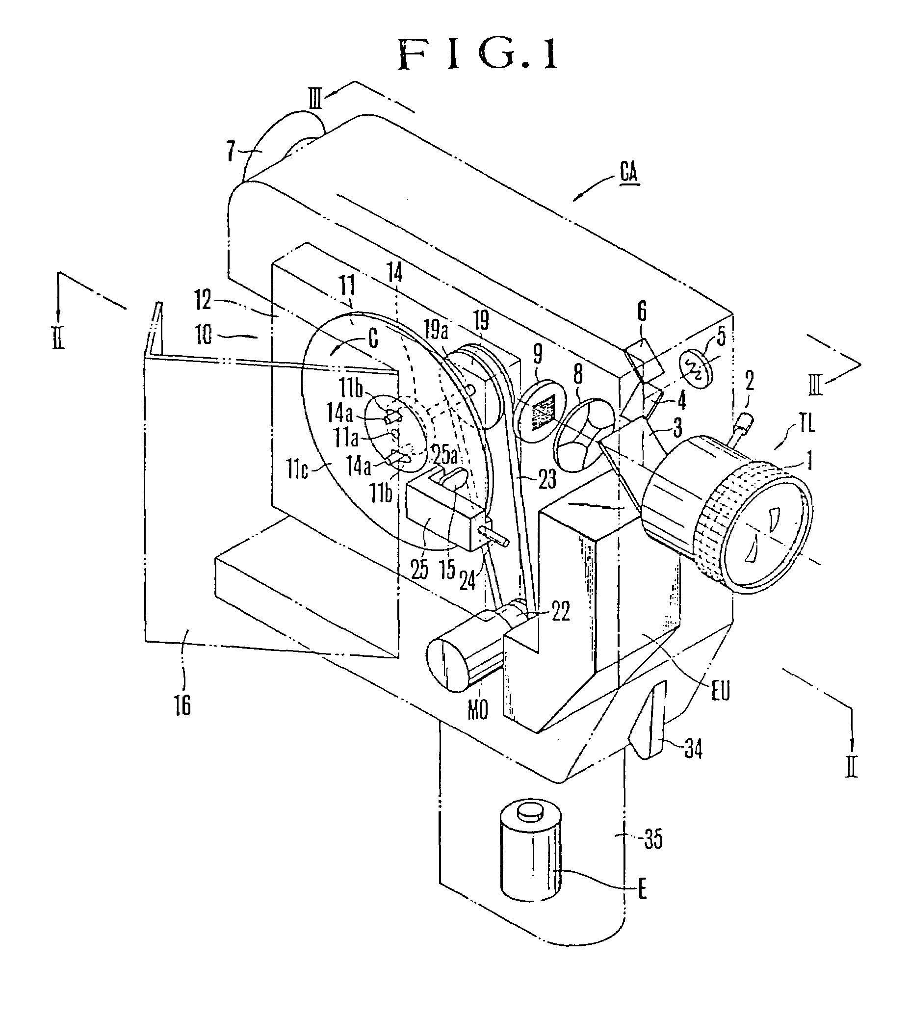
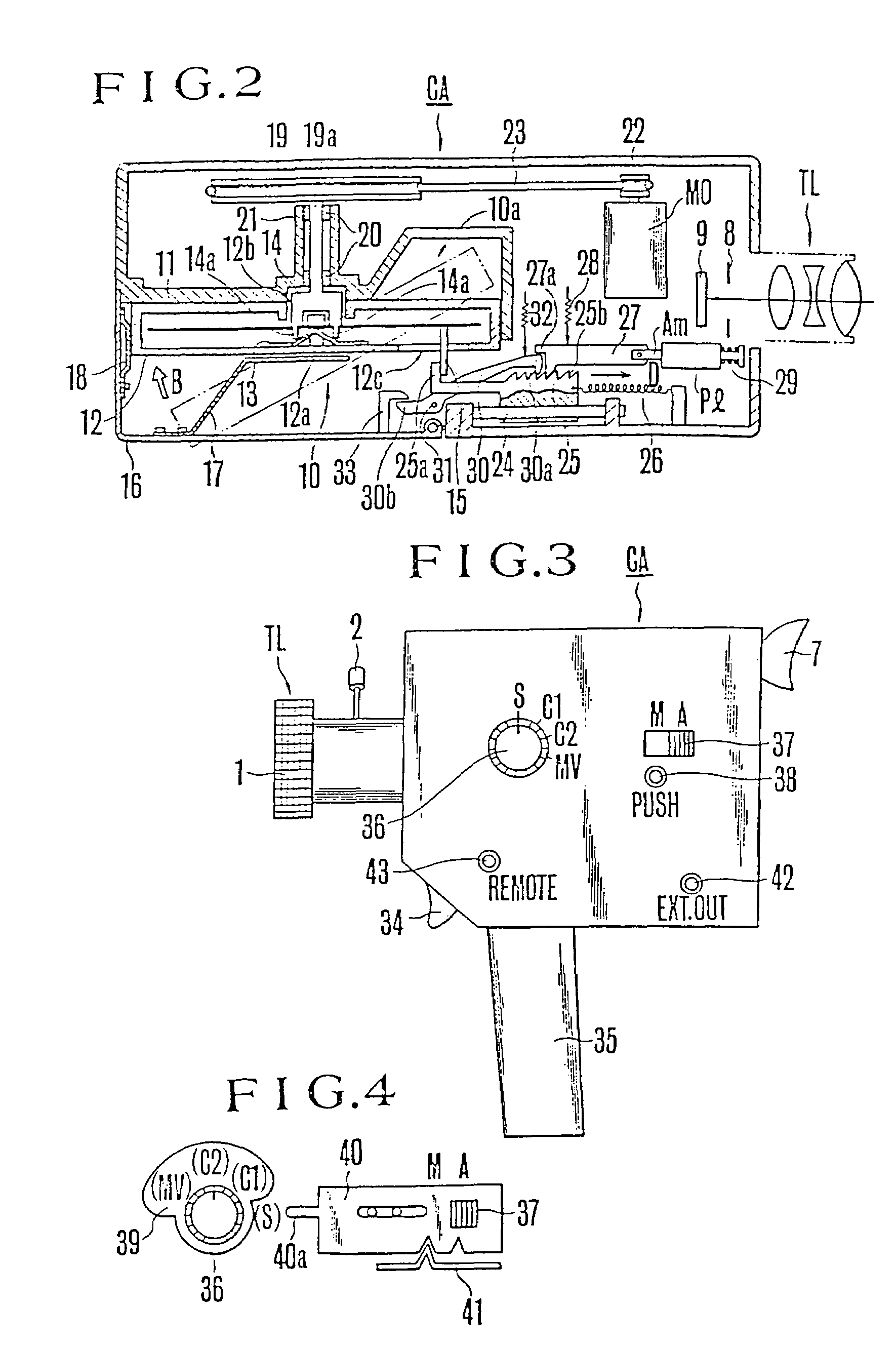
[0041]The embodiment described here are examples where the present invention is applied to a handy camera. Referring first to FIGS. 1-3, a reference symbol CA indicates the camera; TL indicates a picture taking lens; a reference numeral 1 indicates a focusing ring; 2 indicates a zooming operation rod; 3 indicates a semi-transparent mirror which is provided for taking out a view finder light and is disposed obliquely within a camera body in the rear of the picture taking lens L; and 4 indicates a semi-transparent mirror provided in the path of a reflection light coming from the mirror 3 for the purpose of taking out a photometric light. A light measuring element 5 is positioned to receive a reflection light of the mirror 4. Behind a total reflection mirror, there is arranged a view finder optical system of a known structure. A reference numeral 7 indicat...


PUM


Abstract

A camera apparatus includes a single release switch member. The single release switch member is for instructing an image capture operation, and selects one of a first operative state and a second operative state. The first operative state is selected when the single release switch member is pushed down to a first depth. The second operative state is selected when the single release switch member is pushed down to a second depth which is deeper than the first depth. The camera apparatus selects a recordable portion of a recording medium in response to selection of the first operative state, and generates a predetermined electrical signal if the camera apparatus selects the recordable portion of the recording medium. The camera apparatus records the image signal on the selected recordable portion if the second operative state is selected by the single release switch member, and the predetermined electrical signal is generated.

Description

[0001]This is a continuation of application Ser. No. 07 / 766,824, filed Sep. 26, 1991 now abandoned, which in turn is a divisional application of Ser. No. 07 / 758,464, filed Sep. 6, 1991 now U.S. Pat. No. 5,166,840; which in turn is a continuation application of Ser. No. 07 / 630,375, filed Dec. 18, 1990 now abandoned; which in turn is a continuation application of Ser. No. 07 / 512,531, filed Apr. 18, 1990 now abandoned; which in turn is a continuation application of Ser. No. 07 / 187,219, filed Apr. 28, 1988 now abandoned; which in turn is a continuation application of Ser. No. 06 / 731,157, filed May 6, 1985, which is now U.S. Pat. No. 4,783,707, issued Nov. 8, 1988; which in turn is a continuation application of Ser. No. 06 / 331,795, filed Dec. 17, 1981, now abandoned; which in turn is a continuation application of Ser. No. 06 / 030,930, filed Apr. 17, 1979 now abandoned.BACKGROUND OF THE INVENTION[0002]1. Field of the Invention[0003]This invention relates to a picture image recording device...

Claims


Application Information

Patent Timeline
IPC IPC(8): H04N5/225G11B19/02G11B27/22G11B33/10H04N1/21H04N5/77
CPCG11B19/02G11B27/22G11B33/10H04N1/2112H04N1/212H04N5/772G11B2220/20H04N2101/00H04N2201/214Y10S358/906
Inventor NEMOTO, TAKAYUKISUZAKI, KUNIYOSHIUCHIDOI, MASANORISUZUKI, AKIHIKO
Owner CANON KK
Why Eureka
Try Eureka