Membrane structures and their production and use

Inactive Publication Date: 2010-07-08
PHOENIX IPR LTD
View PDF0 Cites 4 Cited by
  • Summary
  • Abstract
  • Description
  • Claims
  • Application Information

AI Technical Summary

Benefits of technology

[0008]A problem with which the invention is concerned is to provide an improved design of monolith which provides large membrane area and simplified manufacturing process.
[0015]A further problem with which the invention is concerned is to provide membrane structures e.g. for use in removal of water from methanol, ethanol, butanol, isopropanol, acetone, THF, diethyl ether or other solvents by pervaporation or gas or vapor permeation, and which lend themselves to more compact and efficient associated plant. In pervaporation water permeates from a feed stream onto and into a membrane and finally though the membrane. On exiting the membrane on the low-pressure permeate side the liquid vaporizes—hence a combination of the two terms PERMeation and Evaporation gives the process of “pervaporation”. Alternatively the membrane can be operated with a pure gaseous or vapor feed stream—gas permeation, in which the membrane operates in the same manner and gives the same high performance.
[0016]In one aspect the invention provides a membrane structure comprising a tubular porous ceramic monolith having tubular conduits each having an internal diameter of about 5 to about 9 mm formed within the monolith with a zeolite membrane formed on the internal surface of each of the conduits, wherein there are five or more conduits disposed in a single annulus. Thus there may be, for example, six or twelve conduits or above in a length of either 600 or 1200 mm, the outer diameter of the support or monolith being e.g. 20 to 50 mm. For example, in a twelve channel monolith having 6 mm circular channels with a 2 mm minimum spacing between each channel and a 4 mm spacing between each channel and the outer cylindrical surface of the monolith, the outside diameter of the monolith may be of the order of 45 mm. In a further embodiment there is provided a four-channel monolith in which the herein specified spacing between the channels and between each channel and the outside of the monolith is followed whereby there is increased material at the centre of the monolith and hence increased mechanical strength and in particular increased stiffness against flexing during use.
[0019](b) greater rigidity and hence resistance to flexing at high feed flow rates through the monolith as the middle part of the tube is now porous alumina or other ceramic with no middle channels, so that it may be possible to pack more supports / tubes into any given module.
[0020]In embodiments of the invention, each monolith has significantly greater surface area than the monoliths of the prior art, and therefore the demands as to the number of monoliths required to make up a commercially practical pervaporation module of a specific surface area is reduced. Pervaporation modules are rated according to the area of membrane in the module, a 6 m2 membrane area being typical. To achieve this working area of membrane, in the prior art a module (FIGS. 5a-5e and 6) may be of internal diameter about 40 cm and may have 130 supports or monoliths fixed in spaced parallel relationship within its internal volume and extending from end to end of that volume. Increase of the working area of the monolith reduces the number of monoliths required for a module of a given membrane working area, and self-evidently reduces manufacturing costs and parts inventory. Furthermore, the module has a branched tubular housing of stainless steel or other suitable material formed firstly with a through passage and secondly with a branch or cross-flow passage for water or other separated material (depending upon the separation required) that has passed through the membranes and through the bodies of the monoliths or supports. For the module to work, each end of the support or monolith has to be sealed to a transverse housing plate or sheet at each end of the through passage (e.g. by a combination of glazed ends to the monolith and O-ring seals). If any of the supports or modules is inadequately sealed, then the module cannot be used because of ethanol, butanol or other material to be treated will by-pass the membranes. Reduction of the number of modules and therefore in the number of seals that have to be made contributes significantly to reliability and ease of manufacture.

Problems solved by technology

It is concerned with the problem of avoiding small membrane defects or pinholes which can have a marked deleterious effect on the performance of a membrane and can render it of little value for many purposes.
It further explains that some existing methods claim that a defect free membrane is obtained on a laboratory scale, but that attempts to provide a substantially defect free membrane on a larger scale have proved unsuccessful.
Although this dry-treatment method may be suitable for laboratory-scale experiments, it is slow and laborious.

Method used


Image

  • Membrane structures and their production and use
  • Membrane structures and their production and use
  • Membrane structures and their production and use

Examples


example

Monolith Material

[0072]Monolith material which may be used comprises ceramic pervaporation substrates or monoliths based on alumina of porosity 34-39%, density 2.4-2.6 g / cm3, and a pore size distribution with an average of maximum pore size≦7 μm, an average of pores, 10%≦5 μm and an average of pores 50% greater than 2.7-4.1 μm.

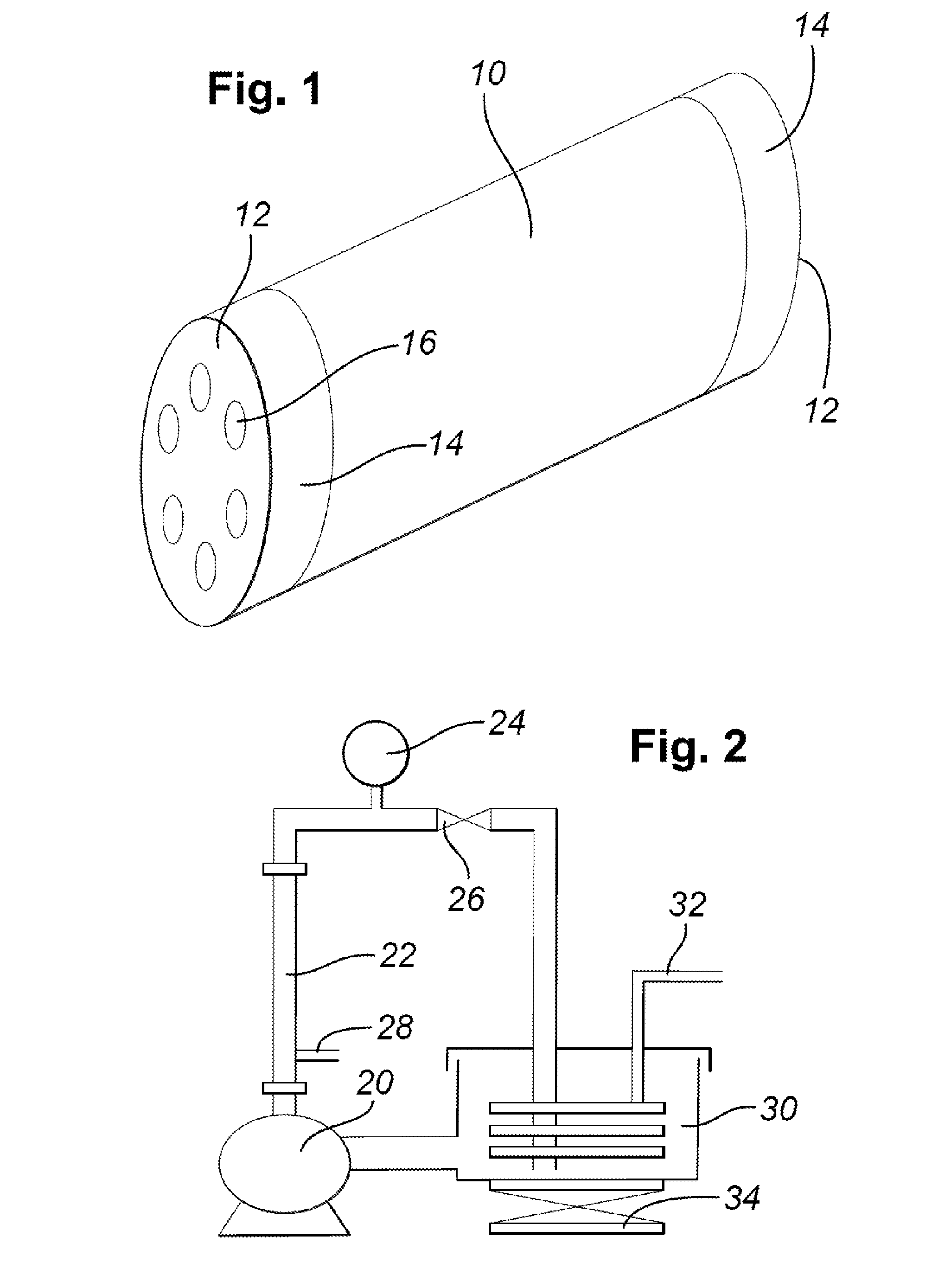
[0073]FIG. 1 is a diagrammatic perspective view of a porous monolith 10 having in this instance six axial conduits 16 disposed equi-angularly in an annular arrangement and opening through opposite end faces 12 of the monolith. Glazed regions 14 cover the end faces 12 and extend partway along at least the outer surface of the monolith as shown to permit fluid-tight O-ring seals to be made to the outer surface of the monolith with a certain amount of end-float to allow for manufacturing tolerances. In this way seals may be made to opposite ends of the monolith 10 so that fluid is forced to flow freely from one end face 12 of the monolith only along the axial con...


PUM

PropertyMeasurementUnit
Diameteraaaaaaaaaa
Lengthaaaaaaaaaa
Lengthaaaaaaaaaa

Abstract

A method is provided for forming zeolite membranes in internal surfaces of a plurality of conduits in a cylindrical porous ceramic monolith, the conduits extending from one end of the monolith to the other and being disposed in a single annulus, said method including a step of: flowing a pre-treatment liquid (50) including a zeolite initiating agent into the conduits; causing at least part of a carrier liquid component of the treatment liquid to flow from the FIG. 4 conduits into and through the body of the monolith to the exterior; and causing zeolite crystals to be deposited in the porous internal surfaces of the conduits as the carrier liquid component flows into the monolith. The substrates may be pre-conditioned for membrane formation by a method which comprises: (a) forming an aqueous suspension of zeolite particles; and (b) passing the suspension alternately (i) through the tubular conduits and (ii) out through the walls of the tubular conduits so as to deposit zeolite particles on the porous inner surfaces of the tubular conduits; wherein the porous substrates are treated in chambers (62) arranged e.g annularly and the suspension is supplied to the chambers from a first common manifold (58) via respective delivery tubes and is recovered via recovery tubes leading to a second common manifold (66), the first and second manifolds and the supply and recovery tubes being configured so that the branch path to and from each chamber is substantially the same. After pre-conditioning, formation of membranes may be by depositing or crystallising a zeolite membrane on the zeolite particles by gel crystallization. A membrane structure is also provided which comprises a tubular porous ceramic monolith having tubular conduits each having an internal diameter of 5 to 9 mm formed within the monolith with a zeolite membrane formed on the internal surface of each of the conduits, wherein either there are five or more conduits disposed in a singe annulus. The invention also provides methods for removal of water from organic liquids salts or other contaminants and methods for the purification of water using the above membrane structures e.g. to remove residual water from ethanol or butanol or to produce high purity water.

Description

FIELD OF THE INVENTION[0001]This invention relates to a membrane structure, to a method of pre-conditioning a multi-conduit monolith for formation of membrane structures in the conduits, to a method of treating a plurality of porous substrates which have tubular conduits formed within them so as to condition the substrates for membrane formation, to a method of treating a plurality of porous substrates which have tubular conduits formed within them so as to form membranes in said conduits, and to a module comprising a multiplicity of the supports or monoliths, and to the removal of water from organic liquids and / or the purification of water e.g. from a contaminated stream.BACKGROUND TO THE INVENTION[0002]U.S. Pat. No. 5,362,522 (Bratton et al., the disclosure of which is incorporated herein by reference) is concerned with the production of membranes and discloses that although there had at the time been extensive research in the field of zeolite membranes, there had been no previous...

Claims


Application Information

Patent Timeline
IPC IPC(8): C02F1/00B01D63/06
CPCB01D63/066B01D67/0051B01D67/0093B01D69/105B01D71/028Y02A20/131B01D2319/04B01D2323/30B01D2323/42C02F1/444B01D2313/04B01D71/0281B01D67/00931B01D2313/041
Inventor BRATTON, GRAHAM JOHNMURTON, COLIN DANNY
Owner PHOENIX IPR LTD
Why Eureka
Try Eureka