
Apparatus for detecting the position of the paintball of a paintball gun

a technology of paintball detection and apparatus, applied in the direction of compressed gas guns, white arms/cold weapons, weapons, etc., can solve the problems of false determination, false detection, false detection, etc., and achieve the effect of avoiding the disturbance of other light sources

Active Publication Date: 2010-07-08
SHENG CHIH SHENG
View PDF10 Cites 2 Cited by
  • Summary
  • Abstract
  • Description
  • Claims
  • Application Information

AI Technical Summary

Benefits of technology

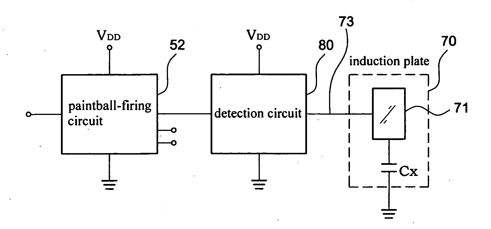
[0011]An object of the invention is to provide an apparatus for detecting the position of the paintball of a paintball gun wherein the feature of the electrification of the paintball is utilized such that the position of the paintball is detected by the electrostatic capacity. In this way, the disturbance by other light sources may be avoided.
[0012]Another object of the invention is to provide an apparatus for detecting the position of the paintball of a paintball gun wherein the detection is conducted by use of the electrostatic capacity without being contaminated or blocked by the paint filling of the paintball. The firing area may be cleaned up once the paintball is fired. The fighting power can be recovered at once. Moreover, it is not required to clean up the inside of the paintball gun after the game.
[0013]A further object of the invention is to provide an apparatus for detecting the position of the paintball of a paintball gun wherein the closer to the induction plate the paintball is positioned, the more accurate is the detection. Besides, the induction plate is large enough so that the paintball won't roll within the firing area. As a result, the detection point can be lowered to a lowest point for an improved detection accuracy.
[0014]Still another object of the invention is to provide an apparatus for detecting the position of the paintball of a paintball gun wherein the electrostatic capacity detection circuit has a low power consumption. In other words, it consumes only a few μA). It is very important for the paintball gun powered by batteries. The service life of the batteries can be prolonged. Moreover, it is not required to replace the batteries frequently. Thus, an environment protection function may be fulfilled.

Problems solved by technology

The reflective type easily causes a false determination due to the color of the paintball 20.
However, the blocking type sensors still have the following drawbacks in use:1. The interference of other light sources: The sun daylight and the artificial light source include a spectrum of infrared, visible light, and ultraviolet.
If the other light sources fall on the optical receiver and if the light intensity is so great that the optical receiver does not work due to the light saturation, a false determination may take place since the detection circuit is not properly responsive to the light falling on the optical receiver.
The light-blocking type paintball detection circuit may make a false determination if the light is strong enough.
The user will be disappointed when the light-blocking type paintball detection circuit does not work due to the light disturbance.
In addition, the light or paintball detection circuit may also make a false determination when the gun barrel of the paintball gun is directed to the light source and the light enters from the gun barrel directly into the firing area (if the light is strong enough).2. The light transmitter and receiver are vulnerable to the contamination of the contents of the paintball such that a function failure takes place.
The paint filling of the paintball will fill the openings, thereby blocking the light transmitter and receiver and leading to a function failure when the paintball 20 is unfortunately broken.
It is probable to lead to a function failure of the light-blocking type paintball detection circuit.
The paint filling of the paintball is corrosive.
The paintball gun will be damaged when the paint filling flowing along the openings to enter into the paintball gun is not cleaned up in time.
However, the paint filling is not easily cleaned up at once due to the shape of the openings.
It is not possible to immediately clean it up at the playing field.
The paintball is more easily broken when the paintball gun has a malfunctioned paintball detection circuit.
The push tube may get stuck by the broken shell of the paintball, thereby causing a problematic discharge.
The light travel direction may be unreasonable due to the shape and the angle, thereby considerably reducing the accuracy in determination.
In fact, there are still gaps in the firing area so that the paintball may roll therein.

Method used


Image

  • Apparatus for detecting the position of the paintball of a paintball gun
  • Apparatus for detecting the position of the paintball of a paintball gun
  • Apparatus for detecting the position of the paintball of a paintball gun

Examples


first embodiment

[0028]First of all, referring to FIGS. 5 and 6, an apparatus for detecting the position of the paintball of a paintball gun in accordance with the invention includes a gun barrel 30, a ball-falling tube 40, a gun handle 50, and a high-pressure tank 60.

[0029]The gun barrel 30 internally includes a push tube 32 for firing the paintball 20 from a firing area 31 through a gun tube 33 outward.

[0030]The ball-falling tube 40 is positioned at the periphery of the firing area 31. According to the embodiment, the ball-falling tube 40 is disposed at the top thereof, but should not be limited thereto. There are many other ball-falling tubes 40 that are positioned at the right side of the firing area 31 for preventing the sight line from being blocked. The ball-falling tube 40 is used for the insertion of a paintball-feeding unit 41 such that the paintballs 20 therewithin in the way of freefall or by means of a paintball-pushing unit (not shown) are delivered one after another to the firing area...

second embodiment

[0041]FIG. 9 shows the invention. The components the same to the previous embodiment are marked with the same reference sign. The difference lies in that the electrostatic capacity detection circuit 80 is disposed close to the induction plate 70 within the gun barrel 30 and coupled via an electric wire to the paintball-firing circuit 52 within the gun handle 50.

third embodiment

[0042]FIG. 10 shows the invention. The induction plate 70 and the electrostatic capacity detection circuit 80 are both positioned on the same circuit board P2 within the gun barrel 30. In other words, the induction plate 70 can be electrically coupled to the circuit board P2 by use of the surface-mounting technology. In this way, the transmission wire 73 is not required and can be directly replaced by the copper foil wire. Of course, a terminal piece 71 can be directly formed by the copper foil on the circuit board P2 and then enclosed by the insulated body 72.


PUM


Abstract

An apparatus for detecting the position of the paintball of a paintball gun includes an induction plate responsive to electrostatic capacity. The induction plate is positioned at a corresponding side of the ball-falling tube within the firing area of the gun barrel, and the induction plate consists of a conductive terminal piece and equivalent electrostatic capacity. An insulated body is interposed between the terminal piece and the gun barrel. Besides, an electrostatic capacity detection circuit is electrically coupled to the induction plate for detecting the change of the electrostatic capacity of the induction plate. Moreover, the signal of the change of the electrostatic capacity is transmitted to the paintball-firing circuit for a reliable detection if the paintball accurately reaches the firing area such that the push tube may be actuated in accordance with this information. In this way, an accurate detection is ensured without being disturbed by other light sources. Moreover, an undesired firing action is avoided when the paintball is still not fed in position. In addition, it is not required to clean up the firing area. Furthermore, a low power consumption is achieved.

Description

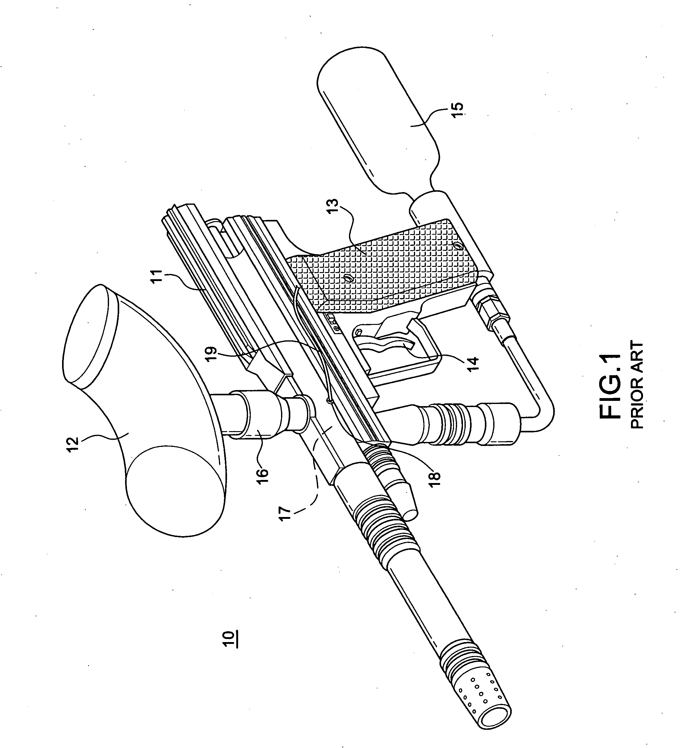
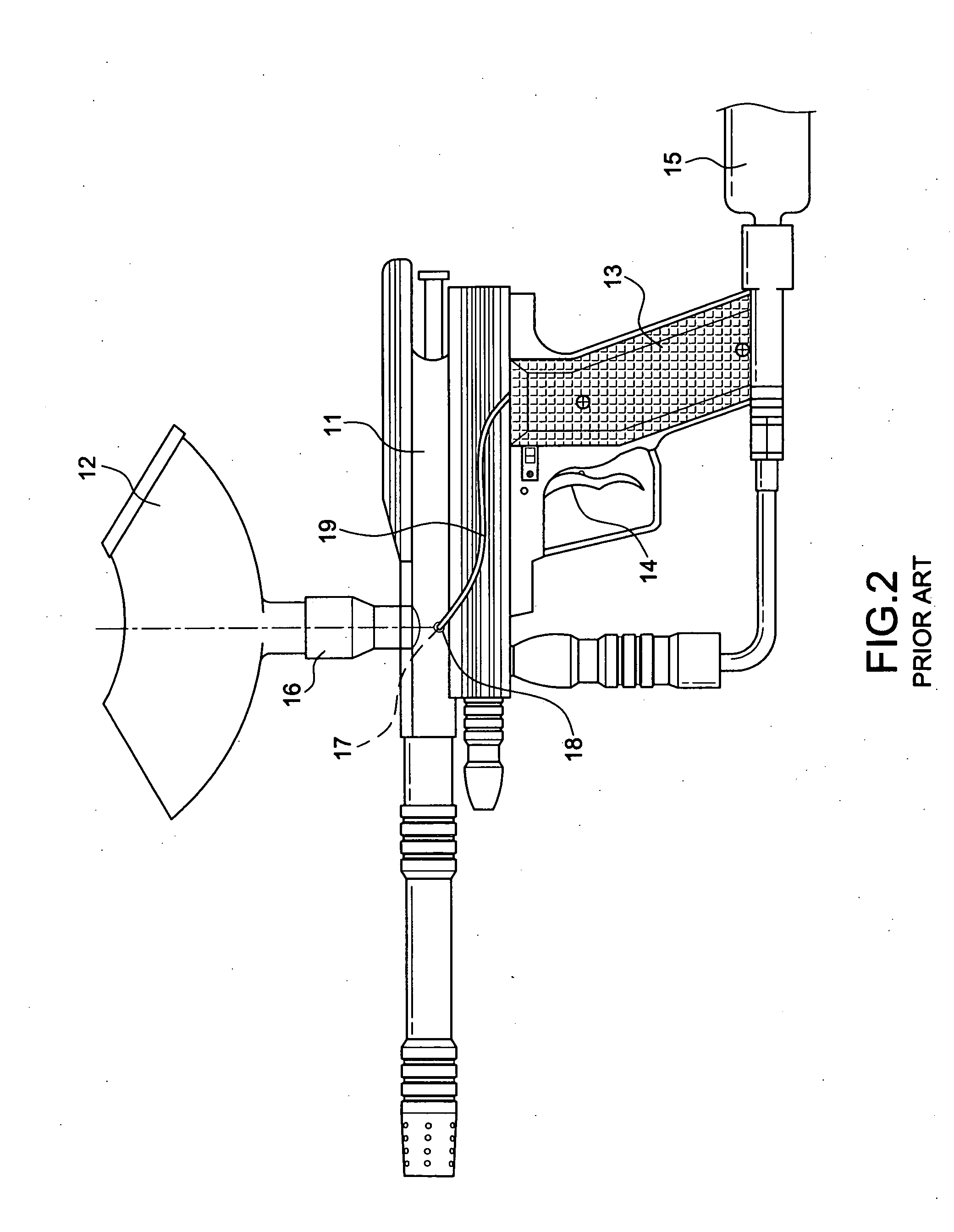
BACKGROUND OF THE INVENTION[0001]1. Field of the Invention[0002]The invention relates to an apparatus for detecting the position of the paintball of a paintball gun, and more particularly to an electrostatic capacity detection apparatus that is positioned in the firing area. Unlike the conventional infrared transmitting / receiving way to create the reflection or interruption state, the feature of the electrification of the paintball is utilized for detecting the fact if the paintball completely reaches the firing area. In this way, an immediate and accurate detection is ensured.[0003]2. Description of the Related Art[0004]In recent years, paintball gun has become a popular outdoor recreational sport. As shown in FIGS. 1 and 2, a paintball gun includes a paintball-feeding unit 12 at the top of the gun barrel 11. Several paintballs are accommodated within the gun barrel 12. A high-pressure tank 15 is attached to the bottom of the gun handle 13. A firing element will be actuated by the ...

Claims


Application Information

Patent Timeline
Patent Type & Authority Applications(United States)
IPC IPC(8): F41B11/00
CPCF41B11/52F41B11/57F41B11/62
Inventor SHENG, CHIH-SHENG
Owner SHENG CHIH SHENG
Learn More