
Vitreous silica crucible manufacturing apparatus

Active Publication Date: 2010-07-08
SUMCO CORP
View PDF37 Cites 11 Cited by
  • Summary
  • Abstract
  • Description
  • Claims
  • Application Information

AI Technical Summary

Benefits of technology

[0010]3. Deterioration of crucible characteristics is prevented and improvement thereof is achieved.
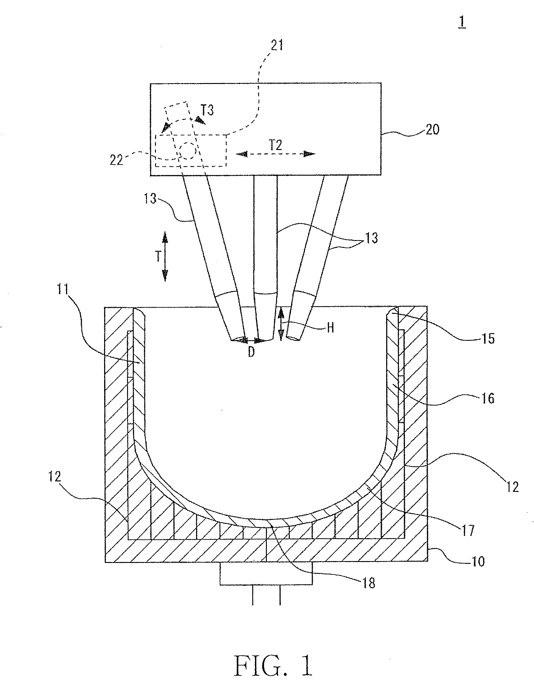
[0027]According to the present invention, since it is possible to prevent electrode vibration, to facilitate arc generation, and to stably generate arc discharge, even in a crucible having a large diameter, it is possible to prevent in-plane unevenness of the characteristics in the inner surface of the vitreous silica crucible melted by generated arc flame or deterioration of the crucible surface characteristics.

Problems solved by technology

However, when a vitreous silica crucible having a large diameter of 30 inches to 40 inches is manufactured, the amount of power necessary for melting quartz powder is increased and thus vibration of an electrode, which generates at the time of start-up of arc discharge, is not negligible.
As a result, the generated arc becomes unstable and influence on the state of the melted quartz powder is not negligible.
In addition, if the electrode vibration is increased, minute pieces stripped from the electrode by the vibration are dropped and thus the characteristics of the vitreous silica crucible deteriorate.
In addition, if the amplitude of the electrode vibration is increased, the electrode may be damaged.
With respect to an arc discharge electrode used for manufacturing the vitreous silica crucible, however, this electrode is exhausted and the composition thereof is emitted to a quartz powder melting ambience, resulting in having influence on the characteristics of the crucible.
In a case of enlarging the diameter of the electrode, power density deteriorates and, as a result, an arc output deteriorates.
In this case, therefore, a processing temperature is decreased and a processed state becomes unstable, thereby having adverse influence on the characteristics of the crucible.
In addition, generated fume (silica vapor) is attached to an upper portion of the electrode due to the decrease in the processing temperature, and the characteristics of the vitreous silica crucible can be deteriorated by the dropping of the attached fume.
Thus, these means cannot be employed so as to prevent the vibration of the electrode.
In addition, the influence of the electrode vibration is caused by the increase in the arc output accompanied by enlargement in the diameter of the crucible.

Method used


Image

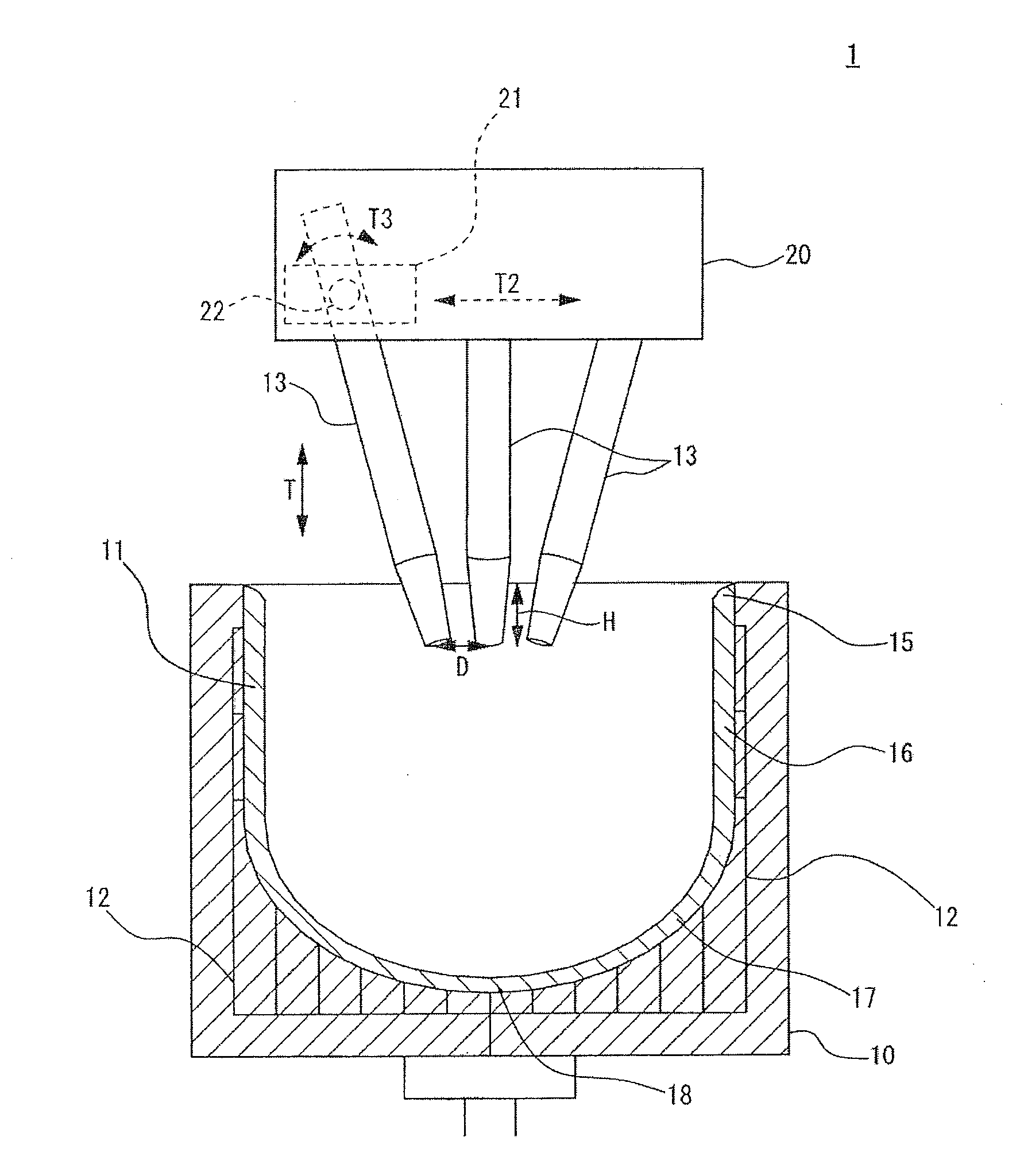
  • Vitreous silica crucible manufacturing apparatus
  • Vitreous silica crucible manufacturing apparatus
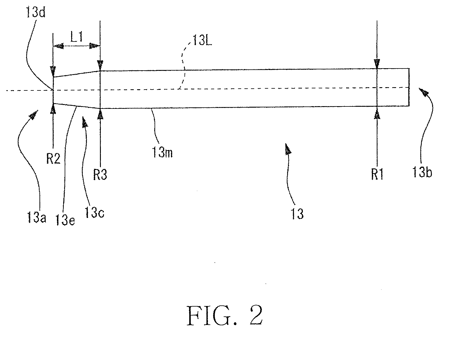
  • Vitreous silica crucible manufacturing apparatus

Examples


example 1

[0072]Using the vitreous silica crucible manufacturing apparatus of the present invention, arc discharge was performed under different conditions of R2 shown in Table 1 so as to manufacture the vitreous silica crucible, and generation of vibration and attachment of fume to the electrode were visually determined and compared. The result is shown in Table 1. Here, in the judgment, a stable degree of arc which is most desirable for manufacture of the vitreous silica crucible was denoted by “⊚”, a desirable degree was denoted by “O”, an undesirable degree was denoted by “x”.

[0073]Crucible diameter: 32 inches

[0074]Output: 3,000 kVA

[0075]Treatment time: 30 minutes

[0076]Electrode shape: front end truncated cone

[0077]θ1 / 2: 10°

[0078]θ2: 4°

[0079]Carbon electrode diameter R1: 50 mm

[0080]Power density P / P2 of carbon electrode: 153 to 611 kVA / cm2

TABLE 1*Exp.Exp.Exp.Exp.Exp.Exp.Exp.ExampleExampleExampleExampleExampleExampleExample1234567θ½ [°]10L1 [mm]120R1 [mm]50R2 [mm]40353043502825R2 / R10.800.7...

example 2

[0082]Arc discharge was performed under the same condition as Example 1 except that R2 is set to a predetermined value of 30 mm and L1 is changed so as to manufacture the vitreous silica crucible, and generation of vibration and attachment of fume to the electrode were visually determined and compared. The result is shown in Table 2.

TABLE 2*Exp.Exp.Exp.Exp.Exp.Exp.Exp.ExampleExampleExampleExampleExampleExampleExample891011121314θ½ [°]10R1 = R3 [mm]50R2 [mm]30L1 [mm]2001501201055530100L1 − x / tan1459565500−25+45(θ½) [mm]VibrationAbsenceAbsenceAbsenceSlightlyPresencePresencePresencepresenceAttachmentAbsenceAbsenceAbsenceAbsenceAbsenceAbsenceAbsenceof fumeJudgment⊚⊚⊚◯XXX*Exp. = Experimental

[0083]From the above result, it can be seen that stable arc can be obtained if L1−X / tan(θ1 / 2) is 50 mm or When L1−X / tan(θ1 / 2) is too large, an undesirable result is obtained in view of cost for manufacturing the electrode. Thus, L1−X / tan(θ1 / 2)<150 mm is preferable.

example 3

[0084]Arc discharge was performed under the same condition as Example 1 except that R2 is set to a predetermined value of 30 mm and R3 is changed so as to manufacture the vitreous silica crucible, and generation of vibration and attachment of fume to the electrode were visually determined and compared. The result is shown in Table 3.

TABLE 3*Exp.*Exp.*Exp.*Exp.*Exp.*Exp.ExampleExampleExampleExampleExampleExample151617181920θ½ [°]10L1 [mm]120R1 [mm]50R2 [mm]30R3 [mm]504543403835R3 / R1 [—]1.000.900.860.800.760.70VibrationWeakAbsenceAbsenceSlightlyPresencePresencepresenceAttachmentAbsenceAbsenceAbsenceAbsenceAbsenceAbsenceof fumeJudgment⊚⊚⊚◯XX*Exp. = Experimental

[0085]From the above result, it can be seen that, in R3 / R1<0.8, arc becomes unstable because vibration is generated.


PUM

PropertyMeasurementUnit
Angleaaaaaaaaaa
Angleaaaaaaaaaa
Lengthaaaaaaaaaa

Abstract

A vitreous silica crucible manufacturing apparatus includes a plurality of carbon electrodes configured to heat and melt raw material powder by arc discharge, and a value of a ratio R2 / R1 of a diameter R2 of a front end of each of the carbon electrodes to a diameter R1 of a base end is set in a range of 0.6 to 0.8. Each carbon electrode has a diameter reduction portion formed at a front end position and reduced in diameter from a diameter R3 of a base end side to the diameter R2 of the front end. When a length of the diameter reduction portion is L1, the diameter of the front end is R2, the diameter of the base end is R1, an angle between the axis lines of the carbon electrodes is θ1, and X=(R1−R2) / 2, a value of L1−(X / tan(θ1 / 2)) is set in a range of 50 to 150 mm.

Description

TECHNICAL FIELD[0001]The present invention relates to a vitreous silica crucible manufacturing apparatus and, more particularly, a carbon electrode used for performing vitrification by heating and melting quartz powder by arc discharge.BACKGROUND OF THE INVENTION[0002]A vitreous silica crucible used for pulling up single crystal silicon is mainly manufactured by an arc melting method. In this method, for example, quartz powder is deposited on an inner surface of a mold made of carbon with a predetermined thickness so as to form a quartz powder molded body of quartz deposition, a carbon electrode is mounted above the quartz powder molded body, and the quartz deposition is heated and vitrified by arc discharge, thereby manufacturing the vitreous silica crucible.[0003]Japanese Patent No. 03647688 discloses a technology of manufacturing a vitreous silica crucible by arc melting, and Japanese Patent Application Laid Open Nos. 2002-68841 and 2001-097775 disclose a technology related to an...

Claims


Application Information

Patent Timeline
IPC IPC(8): C03B19/06
CPCC03B19/095H05B7/085
Inventor FUKUI, MASANORIKISHI, HIROSHIMORIKAWA, MASAKI
Owner SUMCO CORP
Learn More