Grating like optical limiter

a technology of optical limiter and grating, applied in the field of optical power limit, can solve the problems of large volume of liquid to be heated, large amount of energy propagation, and high power requirements, and achieve the effect of limited numerical apertur

Inactive Publication Date: 2010-07-01
KILOLAMBDA TECH
View PDF7 Cites 10 Cited by
  • Summary
  • Abstract
  • Description
  • Claims
  • Application Information

AI Technical Summary

Benefits of technology

[0010]In one embodiment, a reversible optical energy limiting device comprises a waveguide forming an optical path between an input end and an output end, and an optical energy responsive material located in said optical path for reflecting at least a portion of optical energy received from the input end back toward the input end when the optical energy exceeds a predetermined threshold. The optical energy responsive material does not reflect optical energy when it drops below the predetermined threshold, and thus propagation of optical energy from the input end to the output end is automatically resumed when the optical energy drops below the predetermined threshold. The optical energy responsive material may extend across the optical path an acute angle relative to the longitud...

Problems solved by technology

Another problem is laser safety, wherein there are well-defined upper power limits allowed to be emitted from fibers into the open air.
These two issues call for a passive device that will limit the amount of energy propagating in a fiber/waveguide to the allowed level.
The first two of the above-mentioned techniques require very energetic laser beams or light intensities to produce a meaningful limitation.
In the first technique, the volumes of liquid to be heated are large and need high powers.
Another problem with this method is that the liquid is not a good optical medium and distorts the beam.
In the second technique, the n2 coefficient is very small for usable materials and requires very high ele...

Method used


Image

  • Grating like optical limiter
  • Grating like optical limiter
  • Grating like optical limiter

Examples


Embodiment Construction

[0031]Although the invention will be described in connection with certain preferred embodiments, it will be understood that the invention is not limited to those particular embodiments. On the contrary, the invention is intended to cover all alternatives, modifications, and equivalent arrangements as may be included within the spirit and scope of the invention as defined by the appended claims.

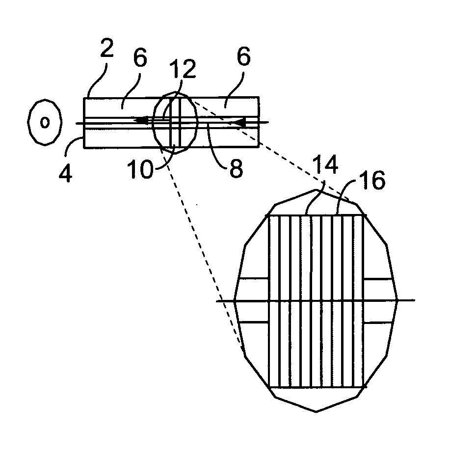
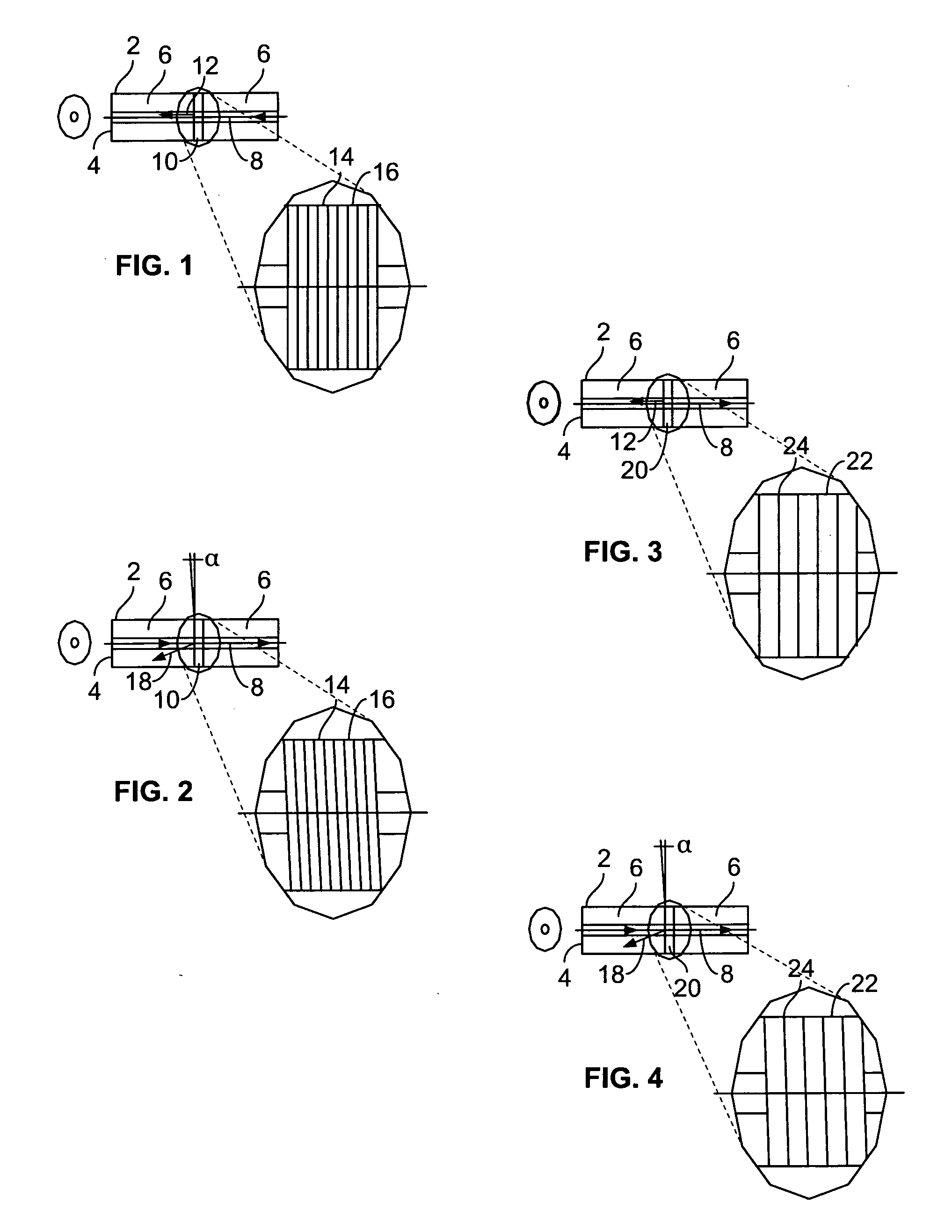
[0032]Turning now to the drawings, FIGS. 1-4 illustrate optical limiter configurations using power-limiting gratings of two types. The first type is an optical limiting solid grating comprising multiple layers of transparent dielectric material, where alternating layers are totally transparent, and intervening layers include a mixture of light absorbing particles. The second type is an optical limiting solid grating comprising alternating layers of totally transparent dielectric material, and intervening layers of a thin, nanometer-thickness, partially-light absorbing material.

[0033]In the fir...


PUM


Abstract

A reversible optical energy limiting device comprises a waveguide forming an optical path between an input end and an output end, and an optical energy responsive material located in the optical path for reflecting at least a portion of optical energy received from the input end back toward the input end when the optical energy exceeds a predetermined threshold. The optical energy responsive material does not reflect optical energy when it drops below the predetermined threshold, and thus propagation of optical energy from the input end to the output end is automatically resumed when the optical energy drops below the predetermined threshold. The optical energy responsive material may extend across the optical path an acute angle relative to the longitudinal axis of the optical path so that back-reflected light does not re-enter the optical system.

Description

FIELD OF THE INVENTION[0001]The present invention relates to optical power limiting, and more particularly, to an optical power limiting passive device and to a method for limiting optical power transmission.BACKGROUND OF THE INVENTION[0002]Optical limiters are devices designed to have high transmittance for low-level light inputs and low transmittance for high power. Since the development of the first lasers, passive optical limiters have been researched and concepts have been tested to protect optical sensors against laser peak-power induced damage. The first optical limiters for CW lasers were based on thermal lensing in absorbing bulk liquids, i.e., local heating in an imaging system reduced the index of refraction, causing “thermal blooming” and resulting in a beam that was no longer focused. Other methods have been suggested for limiting pulsed laser sources such as reverse saturable absorption, two-photon and free carrier absorption, self-focusing, nonlinear refraction and in...

Claims


Application Information

Patent Timeline
IPC IPC(8): G02B6/34G02B6/26
CPCG02B6/266G02F1/0147G02F2201/30G02F2203/52
Inventor ORON, RAMDONVAL, ARIELANEMET, BOAZNEVO, DORONORON, MOSHE
Owner KILOLAMBDA TECH
Why Eureka
Try Eureka