
Valley-mode switching schemes for switching power converters

a technology of switching power converters and valley-mode switching schemes, which is applied in the direction of power conversion systems, dc-dc conversion, instruments, etc., can solve the problems of increasing switching loss, increasing switching stress, and increasing the amount of electromagnetic interference (emi) produced by the switch, so as to prevent the resonant characteristics of the switch-mode power converter

Active Publication Date: 2010-07-01
DIALOG SEMICONDUCTOR INC
View PDF13 Cites 51 Cited by
  • Summary
  • Abstract
  • Description
  • Claims
  • Application Information

AI Technical Summary

Benefits of technology

[0009]Thus, the improved VMS scheme according to embodiments herein enables low-voltage switch operation without restricting the control scheme of the switch-mode power converter. Furthermore, the improved VMS scheme prevents resonant characteristics of the switch-mode power converter from dictating switching frequencies utilized by the power converter, and supports BJT-based power switching in the switch-mode power converter.

Problems solved by technology

The power losses associated with switch operation, referred to as switching losses, represent a significant source of power dissipation and therefore a significant source of inefficiency within conventional switch-mode power converters.
In addition to increasing switching loss, large rates of change for voltages and / or currents (i.e., dv / dt and / or di / dt) at the time of switch transition increase stress upon the switch and the amount of electromagnetic interference (EMI) produced by the switch.
However, conventional VMS schemes are inadequate for several reasons.
These changes in switching frequency result in increased EMI emissions and make conventional VMS schemes compatible only with control schemes that utilize a variable switching frequency such as pulse frequency modulation (PFM) control schemes.
Furthermore, conventional VMS schemes require significant fundamental modification to feedback control schemes used by the switch-mode power converters to regulate signals such as output voltage and output current.
Conventional VMS schemes also do not account for losses associated with turning off the power switch.
Moreover, the high switching frequencies typically required by conventional VMS schemes (e.g., 130 kHz) make them unsuitable for switch-mode power converters that utilize one or more slow power switches such as bipolar junction transistors (BJTs).

Method used


Image

  • Valley-mode switching schemes for switching power converters
  • Valley-mode switching schemes for switching power converters
  • Valley-mode switching schemes for switching power converters

Examples


Embodiment Construction

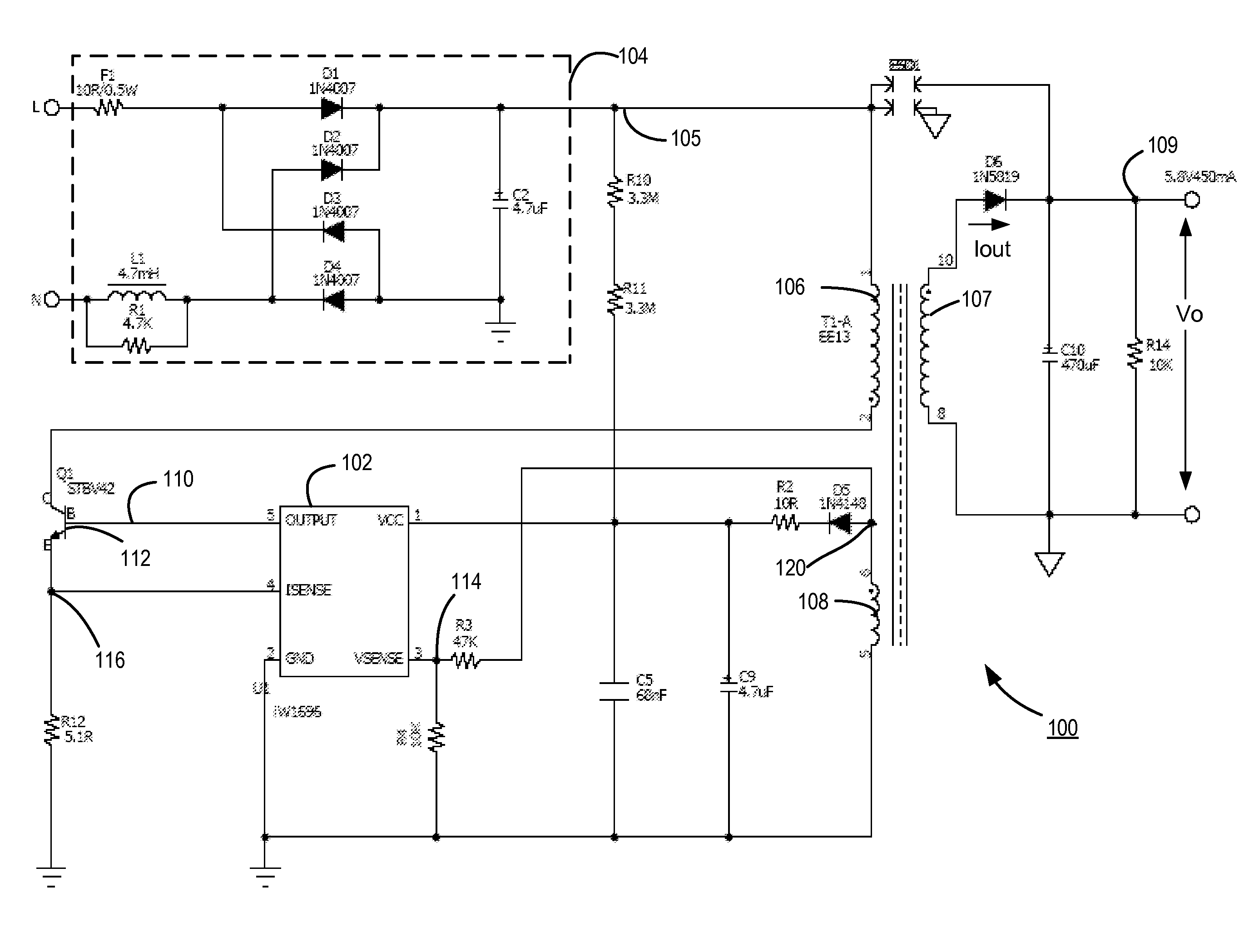
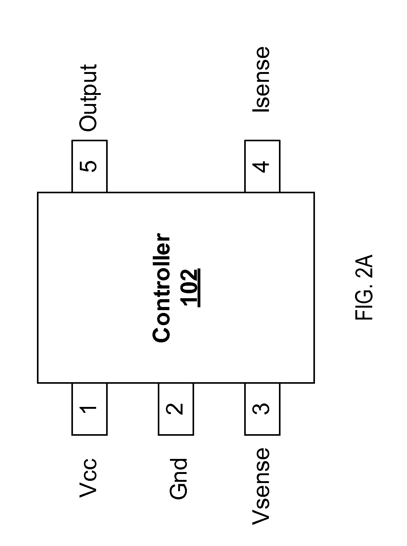
[0017]The Figures (FIG.) and the following description relate to preferred embodiments of the present invention by way of illustration only. It should be noted that from the following discussion, alternative embodiments of the structures and methods disclosed herein will be readily recognized as viable alternatives that may be employed without departing from the principles of the present invention.

[0018]Reference will now be made in detail to several embodiments of the present invention(s), examples of which are illustrated in the accompanying figures. It is noted that wherever practicable similar or like reference numbers may be used in the figures and may indicate similar or like functionality. The figures depict embodiments of the present invention for purposes of illustration only. One skilled in the art will readily recognize from the following description that alternative embodiments of the structures and methods illustrated herein may be employed without departing from the pr...


PUM


Abstract

An improved valley-mode switching (VMS) scheme and circuitry for implementing the improved VMS switching scheme in a switch-mode power converter are disclosed. For a given switching cycle, a desired switch turn-on time is determined based on a pulse width modulation, pulse frequency modulation, or other suitable power converter control scheme. Also, one or more times corresponding to local minimums (valleys) are predicted for the voltage across a power switch of the switching power converter. The power switch is turned on at a valley immediately subsequent or otherwise subsequent to the desired switch time determined according to the power converter control scheme. Thus, the improved VMS scheme enables low-voltage switch operation to reduce switching loss and EMI noise without restricting the control scheme of the power converter.

Description

CROSS-REFERENCE TO RELATED APPLICATION[0001]This application claims priority under 35 U.S.C. §119(e) from co-pending U.S. Provisional Patent Application No. 61 / 141,600, entitled “Valley-Mode Switching Schemes for Switching Power Converters,” filed on Dec. 30, 2008, which is incorporated by reference herein in its entirety.BACKGROUND[0002]1. Field of the Invention[0003]The present invention relates to improved valley-mode switching schemes for switch-mode power converters.[0004]2. Description of the Related Art[0005]Each time a switch, such as a transistor, is turned on or off, energy is dissipated in proportion to the current and voltage being switched. The power losses associated with switch operation, referred to as switching losses, represent a significant source of power dissipation and therefore a significant source of inefficiency within conventional switch-mode power converters. In addition to increasing switching loss, large rates of change for voltages and / or currents (i.e....

Claims


Application Information

Patent Timeline
IPC IPC(8): H02M3/335
CPCH02M3/157H02M3/33507H02M3/28
Inventor LI, YONGBUI, HIEN HUUZHENG, JUNJIEKESTERSON, JOHN WILLIAM
Owner DIALOG SEMICONDUCTOR INC
Learn More