
Combined surface cooler and acoustic absorber for turbomachines

a technology of surface cooler and acoustic absorber, which is applied in the direction of machines/engines, efficient propulsion technologies, light and heating apparatus, etc., can solve the problems of reducing the surface area available for acoustic liner, sink space occupation, brick style heat exchangers being ineffective, etc., to enhance acoustic absorption and heat transfer

Active Publication Date: 2010-06-24
GENERAL ELECTRIC CO
View PDF13 Cites 25 Cited by
  • Summary
  • Abstract
  • Description
  • Claims
  • Application Information

AI Technical Summary

Benefits of technology

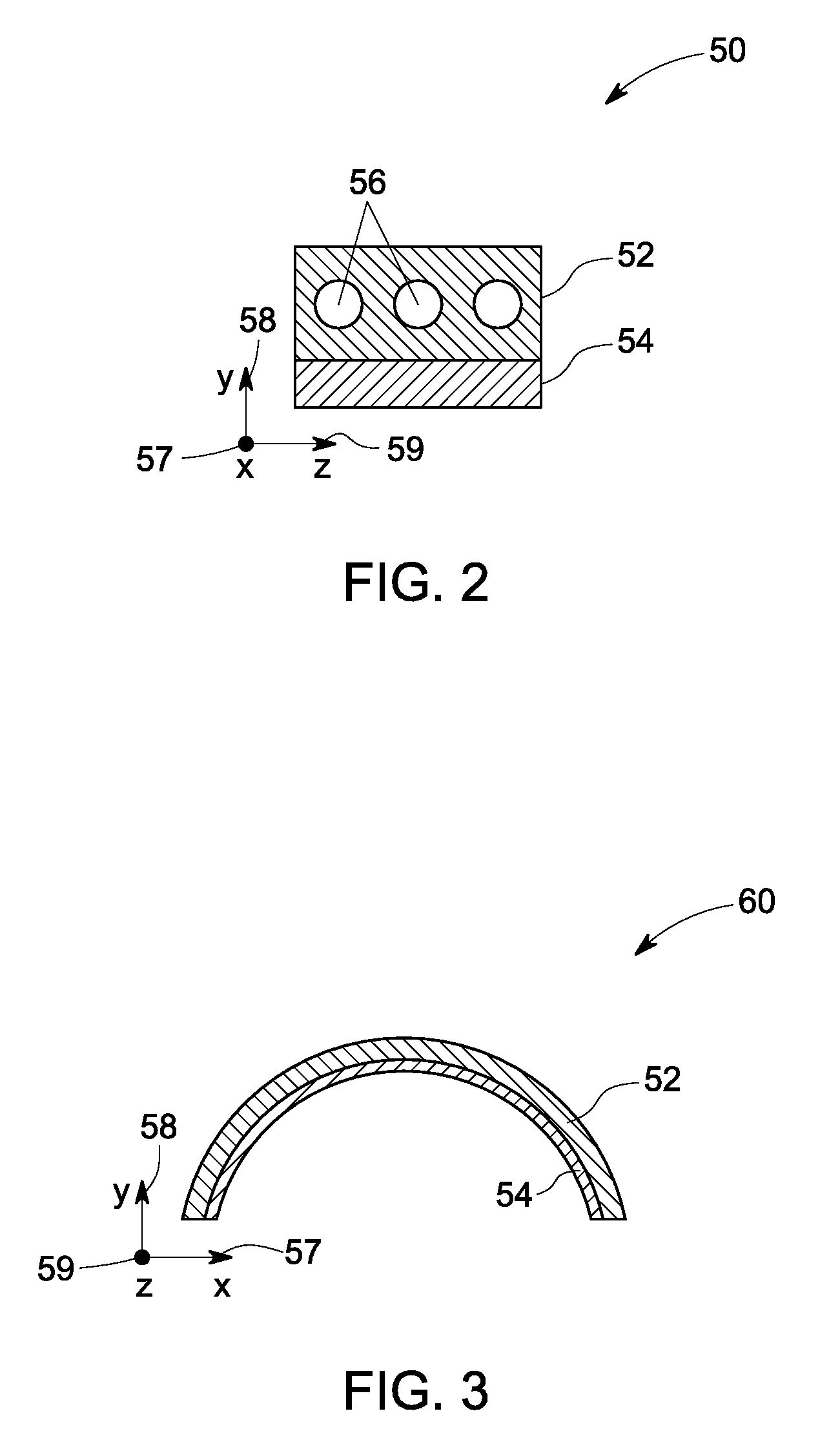
[0005]Briefly in accordance with one aspect of the present technique a surface cooler is provided. The surface cooler comprises an inner layer and an outer layer disposed adjacent to the inner layer and comprising a metal foam, a carbon foam, or a combination thereof, wherein the metal foam, the carbon foam or a combination thereof is configured to augment heat transfer and enhance acoustic absorption.
[0007]In accordance with yet another aspect of the present technique a method of forming a surface cooler is provided. The method provides for forming an inner layer and forming an outer layer adjacent to the inner layer, wherein the outer layer comprises a metal foam, a carbon foam, or a combination thereof, and wherein the metal foam, the carbon foam, or a combination thereof is configured to augment heat transfer and enhance acoustic absorption.
[0008]In accordance with a further aspect of the present technique an engine is provided. The engine comprises a core engine and a surface cooler comprising an inner layer and an outer layer disposed adjacent to the inner layer and comprising a metal foam, a carbon foam, or a combination thereof, wherein the metal foam, the carbon foam or a combination thereof is configured to augment heat transfer and enhance acoustic absorption.

Problems solved by technology

Unfortunately, these heat sinks occupy space that may otherwise be used to house acoustic panels or other materials for further acoustic absorption.
However, these brick style heat exchangers may not be effective when the heat load is high.
Further, more recent techniques employ surface coolers embedded in an outer wall of a bypass duct spanning the entire circumference of an engine, thereby reducing the amount of surface area available for an acoustic liner.

Method used


Image

  • Combined surface cooler and acoustic absorber for turbomachines
  • Combined surface cooler and acoustic absorber for turbomachines
  • Combined surface cooler and acoustic absorber for turbomachines

Examples


Embodiment Construction

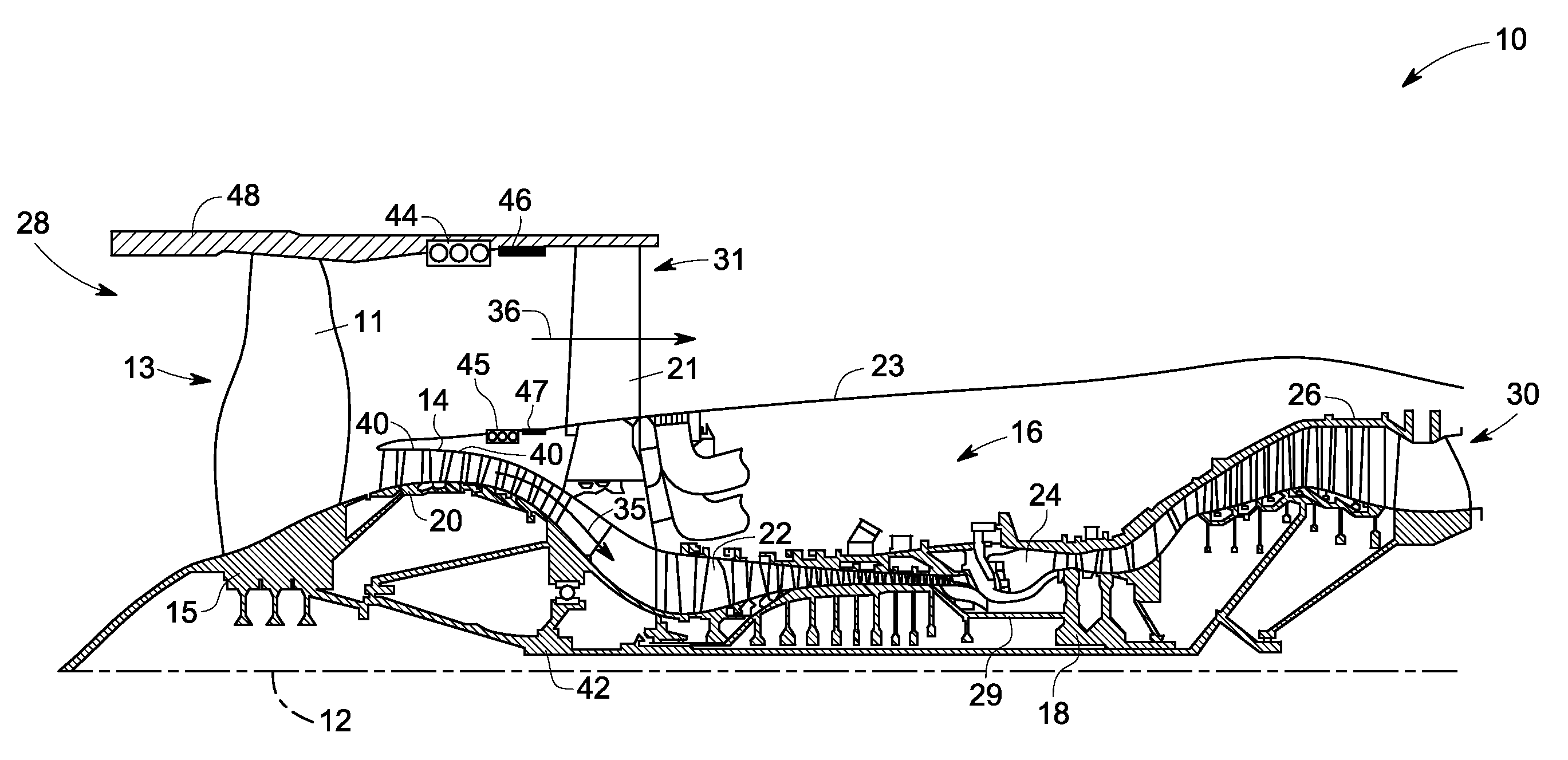
[0029]Embodiments of the present invention relate to surface coolers and more particularly to enhanced surface coolers for use in a nacelle of an engine such as an aircraft engine. The exemplary surface coolers may also be utilized in acoustic absorption as well as for providing efficient cooling. Further, the term “surface coolers” as used herein, may be used interchangeably with the term “heat exchangers.” As used herein, the surface coolers are applicable to various types of turbomachinery applications such as, but not limited to, turbojets, turbofans, turbo propulsion engines, aircraft engines, gas turbines, steam turbines, wind turbines, and water turbines.

[0030]FIG. 1 is a schematic illustration of an exemplary aircraft engine assembly 10 in accordance with the present invention. Reference numeral 12 may be representative of a centerline axis 12. In the exemplary embodiment, the engine assembly 10 includes a fan assembly 13, a booster compressor 14, a core gas turbine engine 1...


PUM

PropertyMeasurementUnit
thicknessaaaaaaaaaa
thicknessaaaaaaaaaa
diameteraaaaaaaaaa

Abstract

A surface cooler for turbomachines is provided. The surface cooler comprises an inner layer and an outer layer disposed adjacent to the inner layer and comprising a metal foam, a carbon foam, or a combination thereof, wherein the metal foam, the carbon foam or a combination thereof is configured to augment heat transfer and enhance acoustic absorption. Further, the outer layer comprises a plurality of fins, wherein the plurality of fins is configured to augment heat transfer and enhance acoustic absorption, and wherein the plurality of fins comprises metal foam, a carbon foam, or a combination thereof.

Description

BACKGROUND[0001]The invention relates generally to turbomachines, and more particularly to the design of enhanced surface coolers for use in the turbomachines.[0002]Aircraft gas turbine engine manufacturers are developing new ways of effectively reducing noise. As will be appreciated, nacelles on jet engines currently utilize liners or acoustic panels to absorb sound produced by the blades and vanes or other turbomachinery elements in the turbofan. These panels are typically located on the nacelle walls. Additionally, it is desirable to place heat sinks in similar locations for removing heat from oil, water, and other coolants. Unfortunately, these heat sinks occupy space that may otherwise be used to house acoustic panels or other materials for further acoustic absorption.[0003]Currently available techniques typically use separate heat exchangers and acoustic absorbers to address the cooling and noise reduction needs of the turbomachines. For example, brick style heat exchangers ar...

Claims


Application Information

Patent Timeline
Patent Type & Authority Applications(United States)
IPC IPC(8): F24H9/00F28F1/10F28F13/00B21D53/02
CPCF01D25/12F02C7/045F02C7/12Y10T29/4935F05D2300/224F05D2300/612Y02T50/675F02K1/827Y02T50/60
Inventor WOOD, TREVOR HOWARDWETZEL, TODD GARRETTLUEDKE, JONATHAN GLENNTUCKER, THOMAS MICHAEL
Owner GENERAL ELECTRIC CO
Learn More