
Fuel cell system and gas leakage detection device

a fuel cell and gas leakage detection technology, applied in the direction of fuel cells, fuel cell components, fuel cell grouping, etc., can solve the problem of shortening the time required for leakage detection

Active Publication Date: 2010-06-17
TOYOTA JIDOSHA KK
View PDF5 Cites 19 Cited by
  • Summary
  • Abstract
  • Description
  • Claims
  • Application Information

AI Technical Summary

Benefits of technology

[0009]The fuel cell system of this configuration enables high-speed reduction of the pressure of the fuel gas in the upstream of the variable pressure regulator on the flow path in the flow direction of the fuel gas supply in the course of leakage detection of the fuel gas from the shutoff valve. This arrangement desirably shortens the time required for the leakage detection of the fuel gas from the shutoff valve.
[0011]In the fuel cell system of this application, the low-pressure power generation enables higher-speed reduction of the pressure of the fuel gas in the upstream of the variable pressure regulator on the flow path in the flow direction of the fuel gas supply in the course of leakage detection of the fuel gas from the shutoff valve. This arrangement further shortens the time required for the leakage detection of the fuel gas from the shutoff valve.
[0015]The fuel cell system of this application attains a high volume ratio of a section of the flow path in the downstream of the variable pressure regulator to a section of the flow path between the variable pressure regulator and the high pressure regulator. This arrangement enables higher-speed reduction of the pressure of the fuel gas between the variable pressure regulator and the high pressure regulator on the flow path and thus further shortens the time required for the leakage detection of the fuel gas from the shutoff valve.
[0018]The gas leakage detection device of this configuration enables high-speed reduction of the pressure of the fuel gas in the upstream of the variable pressure regulator on the flow path in the flow direction of the fuel gas supply in the course of leakage detection of the fuel gas from the shutoff valve. This arrangement desirably shortens the time required for the leakage detection of the fuel gas from the shutoff valve.

Problems solved by technology

This arrangement desirably shortens the time required for the leakage detection of the fuel gas from the shutoff valve.

Method used


Image

  • Fuel cell system and gas leakage detection device
  • Fuel cell system and gas leakage detection device
  • Fuel cell system and gas leakage detection device

Examples


embodiment

A. EMBODIMENT

A1. General System Configuration

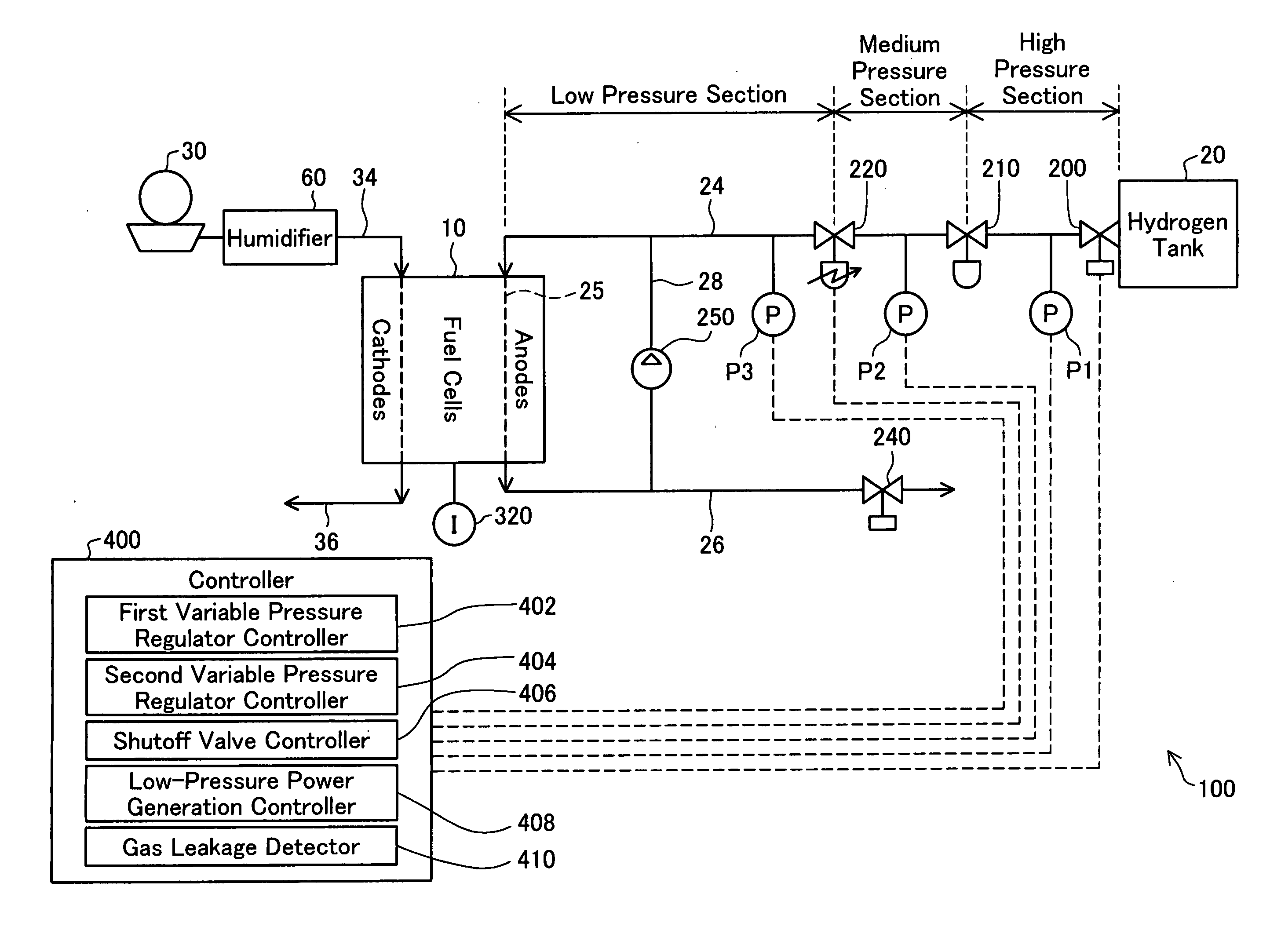
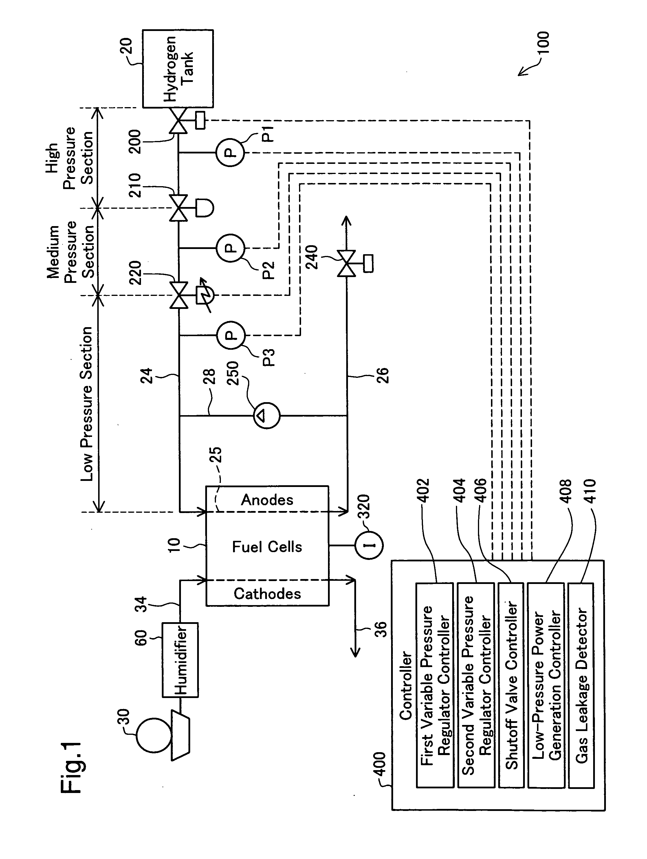
[0030]FIG. 1 is a block diagram schematically illustrating the configuration of a fuel cell system 100 in one embodiment of the invention. The fuel cell system 100 mainly includes fuel cells 10, a hydrogen tank 20, a shutoff valve 200, a high pressure regulator 210, a variable low pressure regulator 220, pressure sensors P1, P2, and P3, a current sensor 320, a blower 30, a controller 400, a humidifier 60, and a circulation pump 250.

[0031]In the fuel cell system 100 of the embodiment, the shutoff valve 200 is checked for any abnormality at the operation stop time of the fuel cell system 100 after ordinary power generation of the fuel cells 10. The abnormality checking process closes the shutoff valve 200 and detects the occurrence of any hydrogen leakage from the shutoff valve 200. This process is hereafter referred to as the hydrogen leakage detection process.

[0032]The fuel cells 10 are polymer electrolyte fuel cells and are arranged to h...

modified example 1

B1. Modified Example 1

[0065]The fuel cell system 100 of the embodiment includes the two regulators, the high pressure regulator 210 and the variable low pressure regulator 220. The technique of the invention is, however, not restricted to the fuel cell system of this configuration, but the high pressure regulator 210 and the variable low pressure regulator 220 may be replaced by one integral regulator ZZ (not shown). The regulator ZZ internally has a medium pressure area corresponding to the medium pressure section of the anode gas supply conduit 24 shown in FIG. 1. This configuration attains a high volume ratio of the low pressure section of the anode gas supply conduit 24 to the internal medium pressure area of the regulator ZZ. In the hydrogen leakage detection process (FIG. 3), the high volume ratio enables higher-speed reduction of the hydrogen gas pressures in the internal medium pressure area of the regulator ZZ and in the high pressure section of the anode gas supply conduit...

modified example 2

B2. Modified Example 2

[0067]The fuel cell system 100 of the embodiment uses the hydrogen tank 20 as the supply source of hydrogen gas. This structure is, however, not essential. One modified structure without the hydrogen tank 20 produces hydrogen through a reforming reaction of an adequate material, for example, an alcohol, a hydrocarbon, or an aldehyde, and supplies the produced hydrogen to the anode flow path 25 in the fuel cells 10 via the shutoff valve 200.


PUM

PropertyMeasurementUnit
electric currentaaaaaaaaaa
pressureaaaaaaaaaa
flow rateaaaaaaaaaa

Abstract

A fuel cell system according to one aspect of the invention is operated in an ordinary mode and in a gas leakage detection mode. The fuel cell system includes fuel cells, a fuel gas supplier configured to supply a fuel gas to the fuel cells, a shutoff valve provided in a flow path for leading a flow of the fuel gas supply from the fuel gas supplier to the fuel cells and configured to shut off the fuel gas supply, and a variable pressure regulator provided in the flow path between the shutoff valve and the fuel cells to regulate a pressure of the fuel gas in a downstream in a flow direction of the fuel gas supply to a variable pressure value. In the ordinary mode, the fuel cell system sets the pressure value of the variable pressure regulator to an ordinary power generation pressure value for ordinary power generation. In the gas leakage detection mode, on the other hand, the fuel cell system closes the shutoff valve, sets the pressure value of the variable pressure regulator to a higher value than the ordinary power generation pressure value, and performs leakage detection of the fuel gas from the shutoff valve. Such setting of the pressure value in the variable pressure regulator desirably enables high-speed reduction of the fuel gas pressure in the flow path between the shutoff valve and the variable pressure regulator.

Description

TECHNICAL FIELD[0001]The present invention relates to a technique of detecting a leakage of a fuel gas from a shutoff valve, which is constructed to shut off the flow of the fuel gas supplied from a gas supplier in a fuel cell system.BACKGROUND ART[0002]Fuel cells consuming a fuel gas (hereafter also referred to as anode gas), such as hydrogen, and oxygen to generate electric power have lately been noted as the novel energy source. In a fuel cell system equipped with such fuel cells, regulators (pressure regulators) are used to lower the pressure of an anode gas supply from a high-pressure anode gas supplier (for example, a hydrogen tank) to an adequate pressure level and then introduce the pressure-regulated anode gas to the fuel cells. The gas supplier is equipped with a shutoff valve (supplier shutoff valve) to allow and stop the supply of the anode gas. The anode gas is flowed from the gas supplier to the fuel cells through a flow path called an anode gas supply conduit. The gas...

Claims


Application Information

Patent Timeline
Patent Type & Authority Applications(United States)
IPC IPC(8): H01M8/04
CPCH01M8/04089H01M8/04388Y02E60/50H01M8/04686H01M8/04753H01M8/04679
Inventor KATANO, KOJISUOMATSU, KOIGOTOMOSADA, NOBUHIRO
Owner TOYOTA JIDOSHA KK
Learn More